Device and method of applying microdroplets to a substrate

Inactive Publication Date: 2002-06-04
HAHN SCHICKARD GESELLSCHAFT FUR ANGEWANDTE FORSCHUNG EV
View PDF17 Cites 7 Cited by
  • Summary
  • Abstract
  • Description
  • Claims
  • Application Information

AI Technical Summary

Benefits of technology

By means of the present invention, a plurality of microdroplets is preferably applied to a substrate simultaneously so that e.g. a biochip for which different biologically relevant substances are applied to a substrate in a regular pattern can be produced inexpensively and reliably. Due to the acceleration of the dosing head, it is possible to drive a microdroplet out of each individual nozzle in a dosing head at the same time, the inertia of the liquid being utilized for this purpose.
The dosing head according to the present invention may comprise one or a plurality of nozzles, the nozzles being arranged at a distance from one another which corresponds to the distance at which the fluid droplets to be applied to the substrate are to be spaced from one another on this substrate. When the nozzles are to be arranged in very closely spaced relationship with one another, i.e. when a very narrow array of different substances is to be produced on the substrate, it will be advantageous when each nozzle is connected to a larger external reservoir via a media line of its own; through these external reservoirs, each nozzle can be supplied with a specific liquid. When the distances between the individual nozzles are large enough for permitting the nozzles to be supplied with liquid by conventional methods, e.g. by standard automatic pipetting devices, the media lines and the external liquid reservoirs can be dispensed with. In this case, the liquid reservoir can be arranged directly above the nozzle.
Such a dosing head can now be decelerated abruptly directly in front of the substrate while carrying out a movement towards the substrate. Due to its inertia and in view of the fact that it is not rigidly connected to the dosing head, the liquid continues this movement and is flung out of the nozzle and onto the substrate. Alternatively, a static dosing head, which is located directly above a substrate, can be accelerated abruptly in a direction away from the substrate. Due to its inertia and in view of the fact that it is not rigidly connected to the dosing head, the liquid cannot follow this movement. It leaves the nozzle in a direction opposite to the direction of movement of the dosing head and is first suspended freely in space before the drops fall onto the substrate due to the force of gravity, the movement of the dosing head being caused by the acceleration away from the substrate. A device can be provided for producing an electrostatic field between the dosing head and the substrate so as to support the application of the droplets to the substrate in this way.
In each of the two above-mentioned cases, it will be advantageous when the acceleration of the dosing head is effected at a position at which the distance between the nozzles in the dosing head and the substrate is very small. This guarantees that, if satellite drops form during the separation of the microdroplets, these satellite drops will merge with the mother drop on the substrate at the latest. Due to the small distance, it is guaranteed that the satellite drops will land on the mother drop even if they left the nozzle at a slightly different angle.

Problems solved by technology

In addition, the method is very susceptible to contaminations of the substrate and of the nozzles.
An essential problem is, however, that it is very expensive and extremely difficult to arrange a large number of nozzles, which have each supplied thereto a different medium, in parallel and in an array, respectively.
The limiting element is in this case the actorics and the media logistics, which cannot be miniaturized to the desired extent.

Method used


Image

  • Device and method of applying microdroplets to a substrate
  • Device and method of applying microdroplets to a substrate
  • Device and method of applying microdroplets to a substrate

Examples


Embodiment Construction

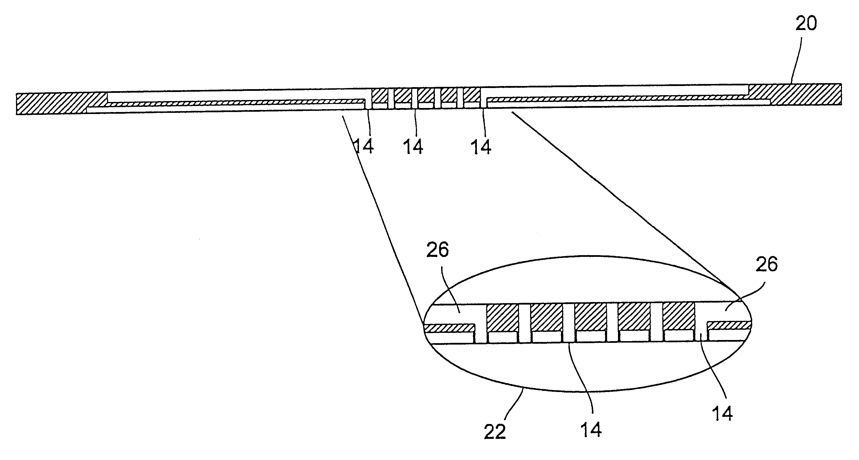
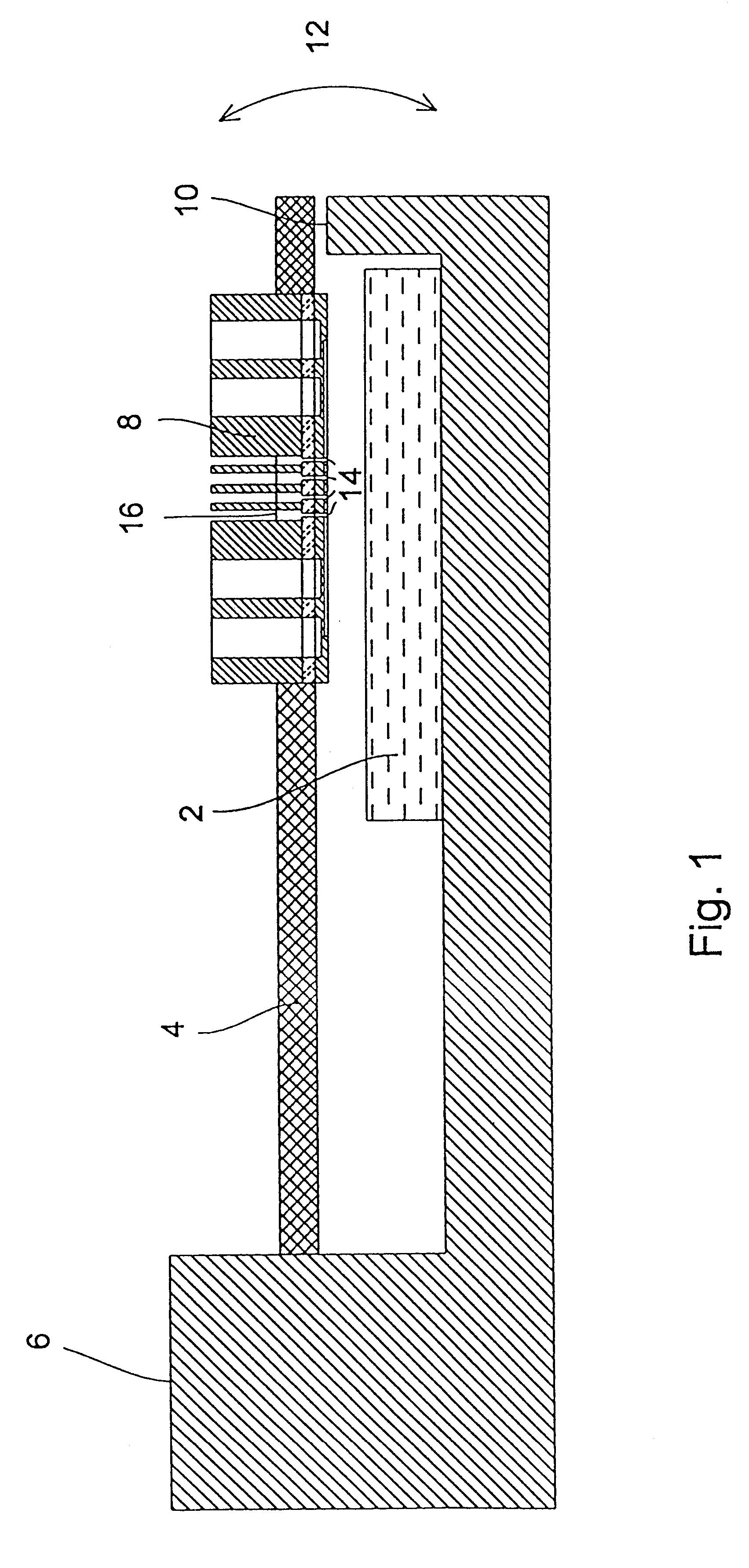
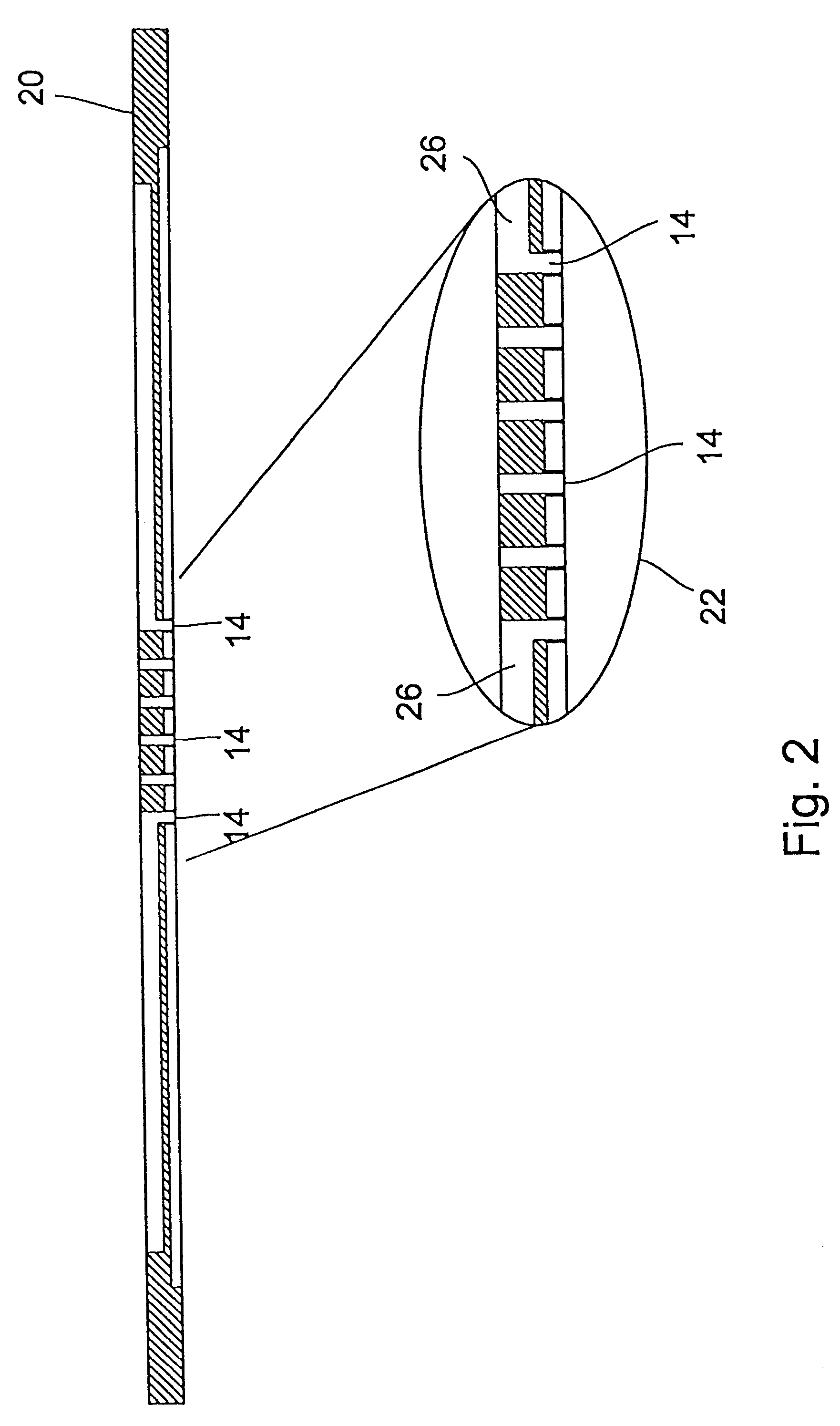
FIG. 1 shows a schematic cross-sectional view of a preferred embodiment of a device according to the present invention used for applying microdroplets to a substrate 2. As can be seen in FIG. 1, a piezo-bending transducer 4 is fixed at one end thereof in a holder 6, a dosing head 8 being attached to the non-fixed end of the piezo-bending transducer 4. Preferred embodiments of the dosing head 8 will be explained in detail hereinbelow making reference to FIGS. 2 to 7b. As can additionally be seen in FIG. 1, the holder 6 is implemented such that it defines a stop 10 by means of which a movement of the piezo-bending transducer 4 and, consequently, of the dosing head 8 is limited downwards in the representation according to FIG. 1, this movement being shown schematically by arrow 12. The dosing head 8 is provided with a plurality of nozzle orifices 14 above which a respective amount of liquid is arranged, as has been indicated schematically by reference numeral 16 and as will be explaine...


PUM


Abstract

A device for applying microdroplets to a substrate includes a dosing head having a nozzle orifice and a liquid storage area in fluid communication with the orifice. A drive applies an acceleration to the dosing head. A quantity of liquid in the storage area cannot follow the acceleration due to its inertia. This inertia causes microdroplets to be driven out of the nozzle onto the substrate. In one embodiment, the dosing head includes a plurality of nozzle orifices each having an associated liquid storage area, so that a plurality of different analytes are deposited on the substrate.

Description

1. Field of the InventionThe present invention relates to a device for applying at least one microdroplet to a substrate and it relates to a dosing head which is adapted to be used in such a device. The present invention relates additionally to a method of applying at least one microdroplet to a substrate. In particular, the present invention relates to devices and methods which are suitable for producing so-called biochips in the case of which a plurality of different analytes are applied to a substrate so as to detect different substances in an unknown sample.2. Description of Prior ArtThe increasing degree to which the genomes of human beings, animals and plants are deciphered creates a large number of new possibilities from the diagnosis of genetically based illnesses to the much faster search for pharmaceutically interesting agents. For example, the above-mentioned biochips will be used in the future for examining food with regard to a large number of possible, genetically modi...

Claims


Application Information

Patent Timeline
IPC IPC(8): B01L3/02B01J19/00F04B19/00G01N35/10B01J4/00G01N33/53C40B60/14G01N1/00G01N1/28G01N33/48G01N33/566G01N37/00
CPCB01J19/0046F04B19/006G01N35/1067B01L3/0268B01J2219/00378B01J2219/00527B01J2219/00605B01J2219/00659Y10T436/2575C40B60/14G01N2035/1041G01N2035/1069
Inventor ZENGERLE, ROLANDHEY, NICOLAUSGRUHLER, HOLGERFREYGANG, MICHAELMULLER, MARTIN
Owner HAHN SCHICKARD GESELLSCHAFT FUR ANGEWANDTE FORSCHUNG EV
Why Eureka
Try Eureka