Three dimensional laser control and tracking system

a tracking system and laser control technology, applied in direction finders using radio waves, instruments, reradiation, etc., can solve the problems of prior art laser-based systems being unable to be used for three-dimensional navigation of mobile objects, and the millimeter level of accuracy is still beyond the reach of satellite navigational systems

Inactive Publication Date: 2002-06-04
TRIMBLE NAVIGATION LTD
View PDF8 Cites 50 Cited by
  • Summary
  • Abstract
  • Description
  • Claims
  • Application Information

AI Technical Summary

Benefits of technology

One aspect of the present invention is directed to a three dimensional multi-unit laser control and tracking system. In one embodiment, the system comprises: (1) a light beacon generating a rotating beam of laser light to cover a three-dimensional site area, and (2) a signal system capable of detecting the laser beam reflected from at least one mobile unit. The signal system generates at least one communication signal including an ID and a positional information of each mobile unit and transmits each communication signal to each mobile unit. Each mobile unit by matching its ID and the timing of reflection of the laser beam is capable to recover its positional information from one such communication signal.
In an alternative embodiment, a three dimensional multi-unit laser control and tracking system comprises: (1) a light beacon generating a rotating and scanning beam of laser light to cover a three-dimensional site area, (2) at least one mobile unit, (3) a signal system capable of detecting the laser beam reflected from each mobile unit, and (4) at least one receiver mounted on each mobile unit. Each mobile unit provides its identification number (ID) upon sensing and reflecting the incoming laser beam. The signal system generates at least one communication signal including an ID and a positional information of one mobile unit and transmits this information to each mobile unit. Each mobile unit by matching its ID and the timing of reflection of the laser beam is capable to recover its positional information from one such communication signal.

Problems solved by technology

However, the millimeter level of accuracy is still beyond the reach of the satellite navigational systems.
However, these prior art laser-based systems can not be used for the purposes of three dimensional navigation of mobile objects because they are configured to determine only one (Z) coordinate of a mobile object.

Method used


Image

  • Three dimensional laser control and tracking system
  • Three dimensional laser control and tracking system
  • Three dimensional laser control and tracking system

Examples


Embodiment Construction

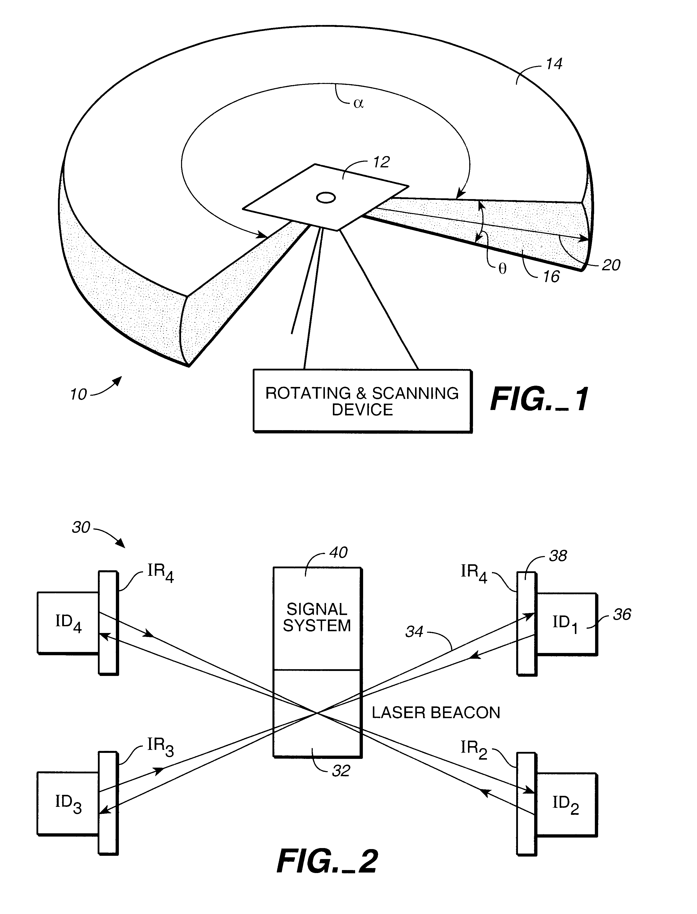
The present invention can be best understood by focusing on a laser beacon (10), as depicted in FIG. 1, that generates a laser beam (20) covering the three-dimensional area (10). The area (10) has a vertical (16) angular window .theta.<180 degrees and a horizontal (12) angular window .alpha.=360 degrees. The laser beam (20) of FIG. 1 can be generated using a rotating laser system with a scanning feature.

Rotating lasers were introduced about twenty-five years ago. The rotating laser system can be implemented when a laser spins in the horizontal plane, or Z-plane, and provide an accurate reference plane with millimeter-precision. The rotating laser emits a laser beam. However, to detect and get benefit of the rotating laser beam, the potential user has to be located within vertical range. The user has to be equipped with the laser receiver capable of receiving the rotating laser beam. The rotating laser beam can be rotated mechanically or optically. In the mechanic embodiment, the mot...


PUM


Abstract

A three dimensional laser tracking and control system is disclosed. The system includes a laser beacon generating a three dimensional rotating and scanning laser beam that covers a three-dimensional area. Each mobile unit has identification number (ID) and is equipped with a intelligent reflector (IR). Each mobile unit uses its intelligent reflector (IR) to communicate to the signal system its ID and the time of illumination by the laser beam. The signal system calculates the three dimensional coordinates for each mobile unit and communicates the positional data back to each mobile unit using the same laser beam during the subsequent rotation cycles.

Description

The current invention is in the field of the position tracking and control systems.DESCRIPTION OF THE BACKGROUND ARTIn the available art of position tracking and control systems, the three dimensional position coordinates of the mobile object can be determined in a variety of ways. In recent years, the global positioning satellite (GPS) receivers and the receivers that use the alternative satellite systems, like GLONASS system, came of age and began to proliferate widely. The autonomous navigational system that includes the satellite receiver and a navigational computer can achieve the 10-meter level of accuracy in the position determination of the mobile object.The differential navigation systems that utilize the differential corrections in addition to the satellite signals can determine the positional information with the meter-range accuracy. The real-time kinematic (RTK) GPS systems that are capable of utilizing in real time not only code abut also the carrier information transm...

Claims


Application Information

Patent Timeline
Patent Type & Authority Patents(United States)
IPC IPC(8): G01S17/00G01S17/74G01S17/42G01S7/00H04B10/22
CPCG01S7/003H04B10/22G01S17/74G01S17/42H04B10/801
Inventor MAYNARD, KURTIS L.
Owner TRIMBLE NAVIGATION LTD
Why Eureka
Try Eureka