

Industrial vault
a technology for industrial vaults and vaults, applied in the field of industrial vaults, can solve the problems of fragile plastic cable rack inserts, damage or destruction, and difficulty in modifying the entire vault, and achieve the effect of reducing the potential for undesired material leakage into the vault and facilitating the insertion of lifting devices
Inactive Publication Date: 2002-06-11
NEEBASIS LLC +1
View PDF73 Cites 25 Cited by
- Summary
- Abstract
- Description
- Claims
- Application Information
AI Technical Summary
Benefits of technology
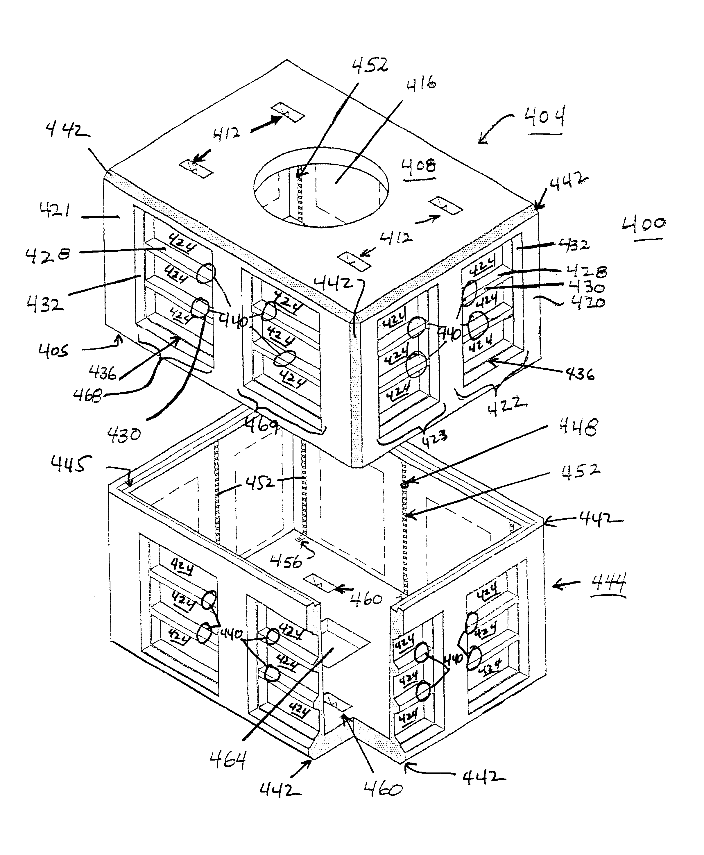
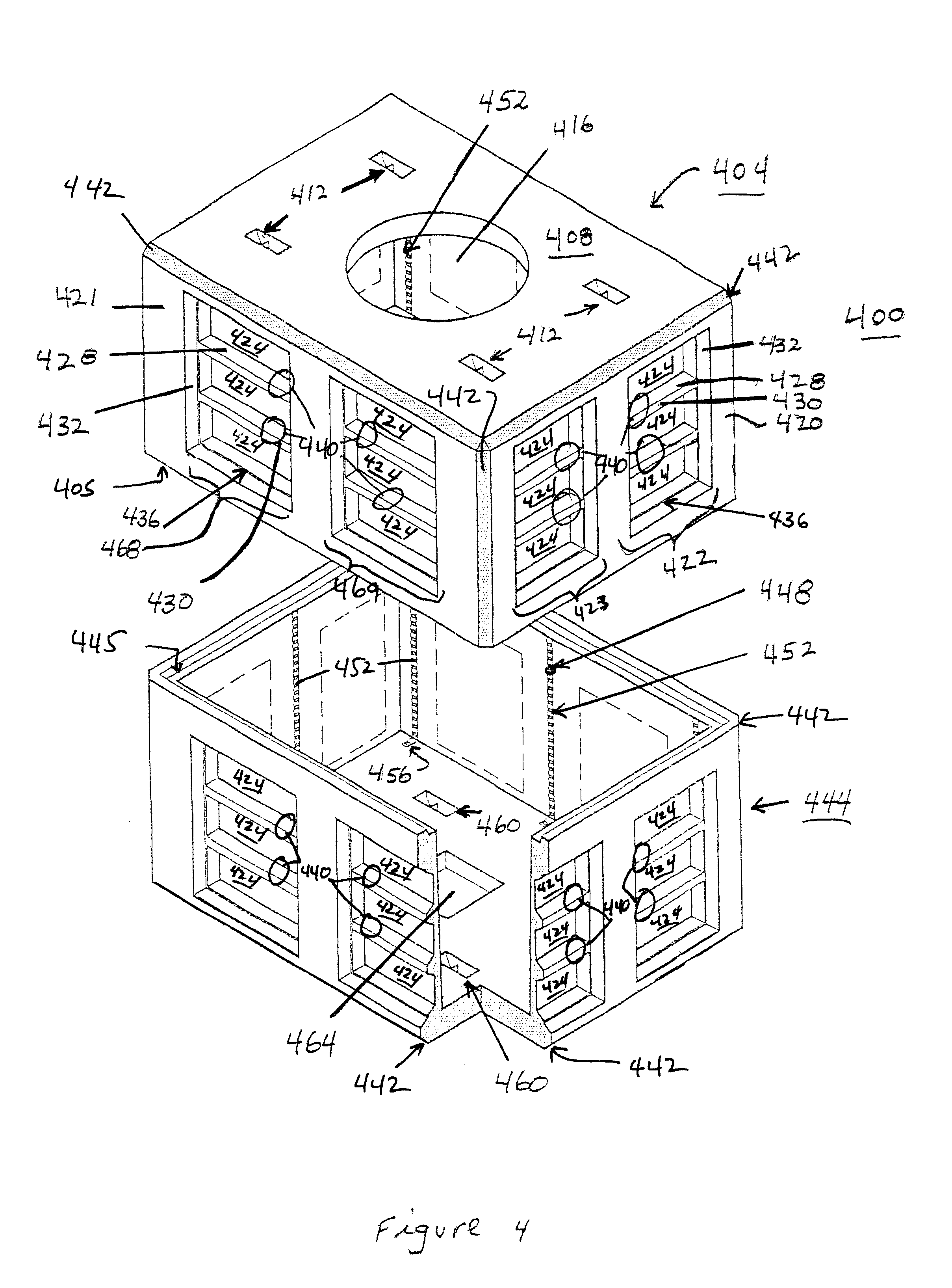
The cast vaults of the present invention have design features that can permit flexibility of installation of terminator plates, conduits and cables. Using the designs described in detail below, a manufacturer can decrease the amount of time and materials needed to manufacture the vaults, can provide for installation of terminator plates, conduits and cables in desired locations in the vault, and can provide cast-in cable racks having built-in ground connections. Many of the desirable features derive from the basic design and construction of the vaults, described herein below. Additional features characteristic of the terminator plates and cable racks can be integrated into the vault design.
By the use of the methods and products of this invention, one can delay the decision about locating conduits until the vault is sited and installed in the field. Thus, to install a vault of the present invention, once a site is determined, an appropriately sized hole can be formed (for underground or partial underground installation) and the vault can be placed therein. Alternatively, if desired, a vault can be placed on a ground-level pad. A location for the terminator plates can be chosen and the appropriate knock-outs can be removed. The vault is then fitted with terminator plates, and conduits are provided. Electrical cables can be installed using the conduits. Subsequently, underground vaults can be backfilled. At some later time, the vault can be exposed, and additional segmented knock-outs can be removed, and additional terminator plates and cable conduits can be placed in the vault walls.
Problems solved by technology
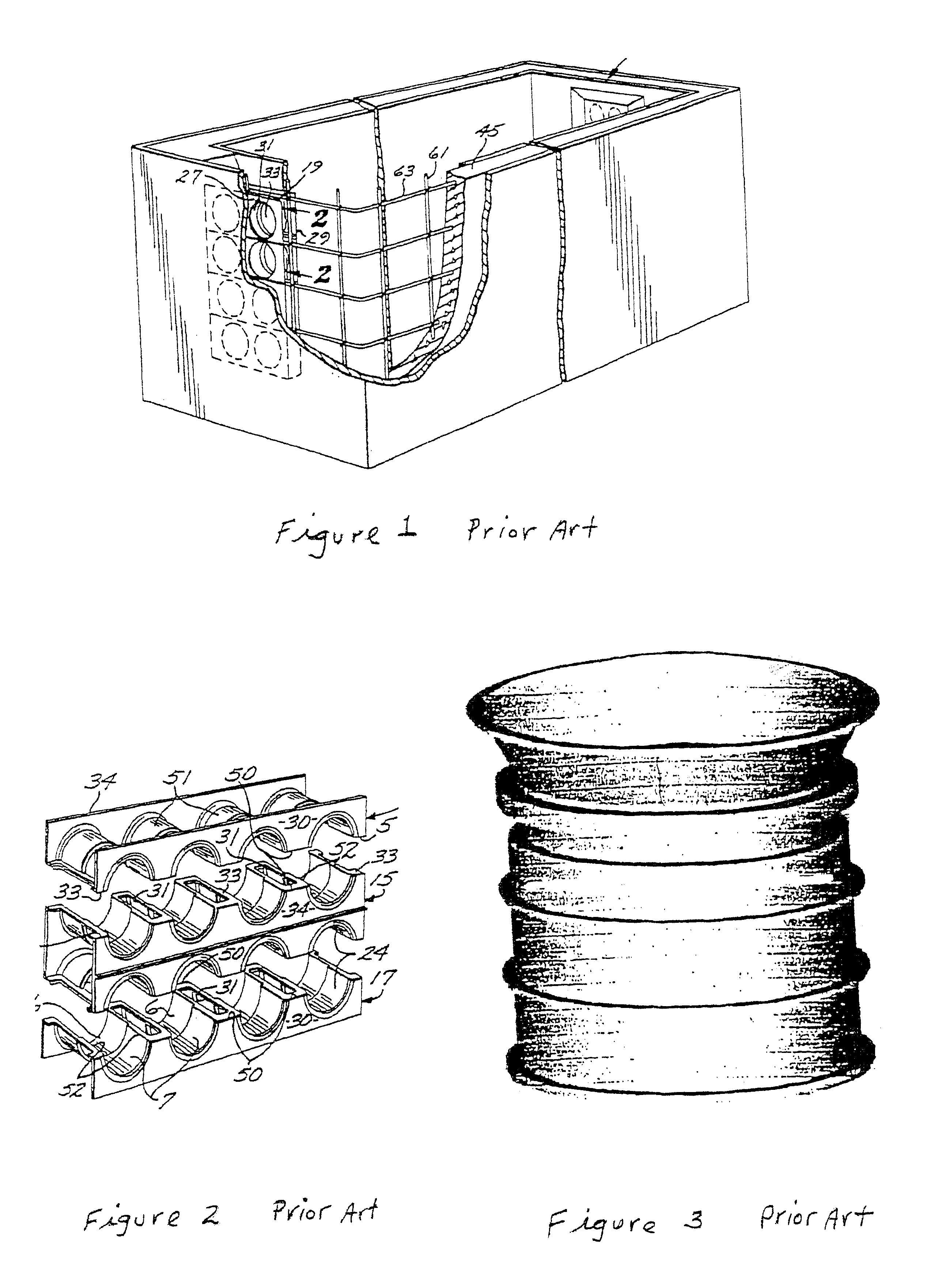
This method results in a plastic cable rack insert which is fragile and can be subject to damage or destruction upon bolting the cable rack to the insert.
This problem can be especially severe if galvanized bolts are used.
Once manufactured, the configuration of the openings and / or terminator plates is fixed; modifications can be difficult to accomplish without replacing the entire vault.
Moreover, neither site-specific nor customer-specific manufacture lend themselves to assembly line production methods.
Thus, the cost of the vault is high and the time lapse between customer order and delivery of the finished vault can be undesirably long.
Therefore, prior art vaults can have substantial disadvantages.
They are not easily manufactured using assembly line methods, they require more time to manufacture, they expose workers to unnecessary risks, and once made, the configurations are fixed which makes modifications difficult.
Moreover, cast-in terminator plates are prone to leak at the concrete-terminator plate boundaries, allowing unwanted substances including water to gain access to the vault.
The introduction of such substances increases the likelihood of short circuiting of electrical components, contamination of devices and corrosion of devices within the vault.
However, this can lead to difficulties in manufacturing that can be overcome by the use of rebar support mounting brackets described below.
After casting, removal of the vault from the form results in breaking the cable rack insert, leaving a threaded portion remaining in the inside wall of the vault.
Method used
View moreImage
Smart ImageViewing Examples

Examples
Embodiment Construction
has been presented for purposes of illustration and description. It is not intended to be exhaustive or to limit the invention to the precise form disclosed, and obviously many modifications and variations are possible in light of the above teaching. The described embodiments were chosen in order to best explain the principles of the invention and its practical application to thereby enable others skilled in the art to best utilize the invention in various embodiments and with various modifications as are suited to the particular use contemplated. It is intended that the scope of the invention be defined by the claims appended hereto.
Login to View More PUM
 Abstract
This invention comprises reinforced industrial vaults with segmented knock-outs having a variety of shapes and orientations. The invention also comprises vaults having cast-in cable racks. The cable racks can be electrically connected to the reinforcing elements during manufacture, providing electrical grounding of electronic equipment placed in the vault. Cable channels can be installed at desired locations by selecting a knock-out, removing the knock-out and installing a terminator plate having cable conduits. Cable conduits can have diaphragms that can be removed to provide additional choices for locating cable channels. Cable channels can be provided in a vault in the field, even if the vault has been already installed.
Description
1. Field of the InventionThis invention relates to industrial vaults.2. Description of the Related ArtIndustrial vaults are widely used as locations for junctions of electrical cables, pipes, and conduits for telephone and electrical power distribution. Typically, vaults are made of concrete and comprise a bottom, sides, and a top. Vaults can include access ports for workers to gain entrance to the vault to install and / or repair the components in the vault. Vaults are cast in forms, or molds, typically made of steel, that define interior and exterior surfaces of the vault. Because vaults are typically placed underground, the walls must have sufficient strength to withstand the vertical and lateral forces exerted by the ground surrounding the vault. The mechanical strength of vaults is increased typically by using reinforcing rods or "rebar" arranged to form a cage. A rebar cage typically includes vertical and horizontal members linked together with wire. A mold surrounds the cage an...
Claims
Login to View More Application Information
Patent Timeline
 Patent Type & AuthorityPatents(United States)
IPC IPC(8): E02D29/12E02D29/00H02G9/00H02G9/10
CPCH02G9/10E02D29/12
InventorELLIOTT, THOMAS P.
OwnerNEEBASIS LLC