Catheter movement control device and method

a technology of movement control device and catheter, which is applied in the direction of catheter, engine diaphragm, diaphragm valve, etc., can solve the problems of severe (or fatal) injury to the patient, difficulty in controlling the insertion of the catheter tube,

Inactive Publication Date: 2002-06-11
MEDICAL TECH OF GEORGIA
View PDF52 Cites 65 Cited by
  • Summary
  • Abstract
  • Description
  • Claims
  • Application Information

AI Technical Summary

Benefits of technology

It is another objective of the present invention to provide a movement control device which will immediately capture the catheter tube when the advancing motion is discontinued to thereby instantaneously prevent any rearward motion of the catheter tube.
It is yet another objective of the present invention to provide a catheter movement control device which includes a pair of wings on the housing that helps prevent axial housing rotation within the package.
The aforesaid and other objectives are realized by providing a catheter movement control device contained within a standard flexible transparent package which includes a cylindrical housing formed from a suitable plastic which defines a catheter tube channel therewithin. Wings positioned on the outer sides of the housing help stabilize the housing to prevent axial housing movement within the catheter package. The catheter package provides a sterile environment for the catheter and a cap on the external housing fitting prevents contaminants from entering the catheter tube. In use, the movement control device is held by the user and the catheter tube is manually manipulated therethrough for insertion into the urethra. Continued forward motion allows the catheter tube to penetrate deeper into the urethra. If resistance is met during insertion, the catheter tube is prevented from substantial rearward movement by the control device. The control device includes a biasing member which holds a tube gripper against a shoulder within the housing. If the catheter tube is urged rearwards, the tube gripper pivots against the shoulder to thereby engage the catheter tube with its radially aligned teeth instantly preventing the catheter tube from such rearward movement. Once the resistance has ceased, the catheter tube again can be moved forwardly through the housing and out of the package a desired depth into the urethra for bladder drainage. Such drainage can be directed into the catheter tube package or, the catheter tube package can be opened at its rear end to act as a conduit for conducting such fluids to a commode or other satisfactory receptacle.

Problems solved by technology

As such catheters have lubricants applied, it is often difficult to control the insertion of the catheter tube which is formed from a lightweight, flexible, polymeric material.
Otherwise, forcing the catheter tube into or through an obstruction may cause significant discomfort, the creation of false passages which may become infected, or may result in severe (or fatal) injury to the patient.

Method used


Image

  • Catheter movement control device and method
  • Catheter movement control device and method
  • Catheter movement control device and method

Examples


Embodiment Construction

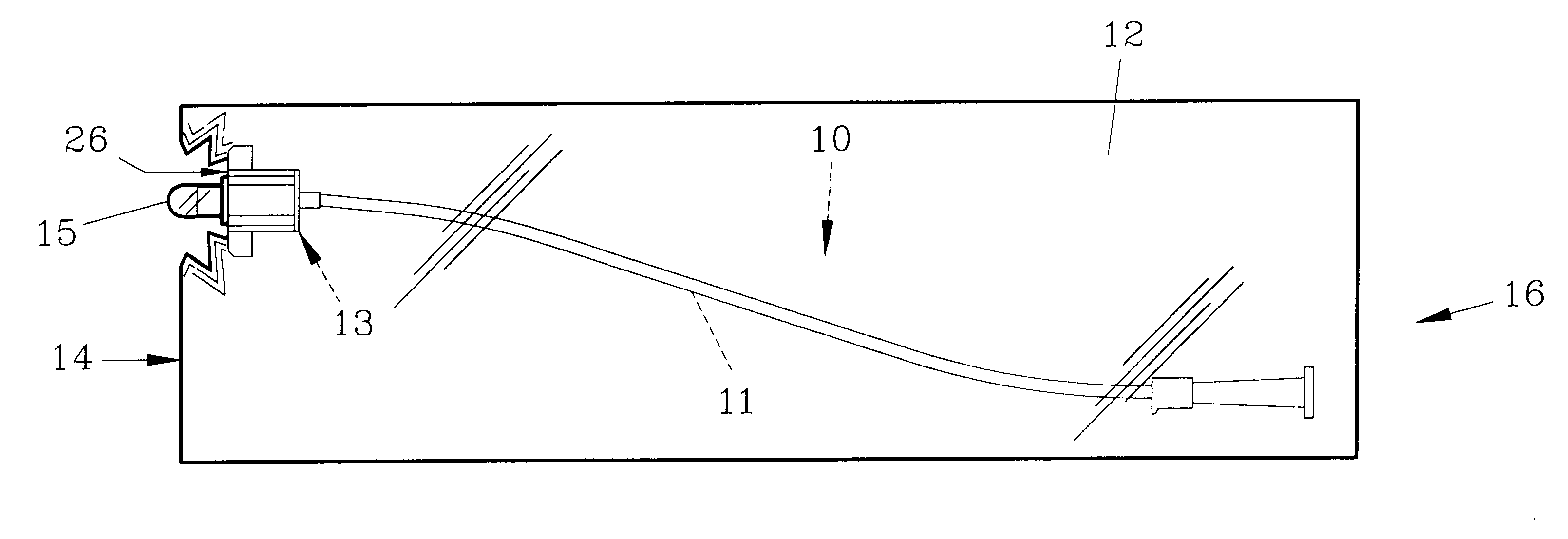
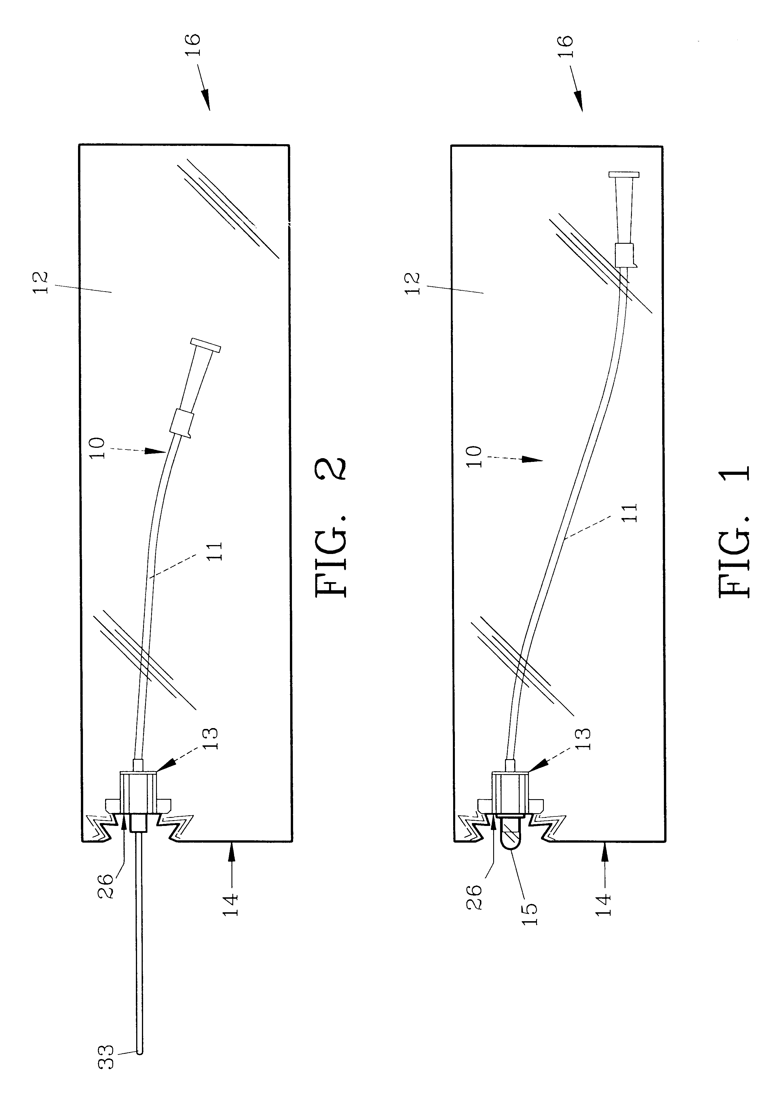
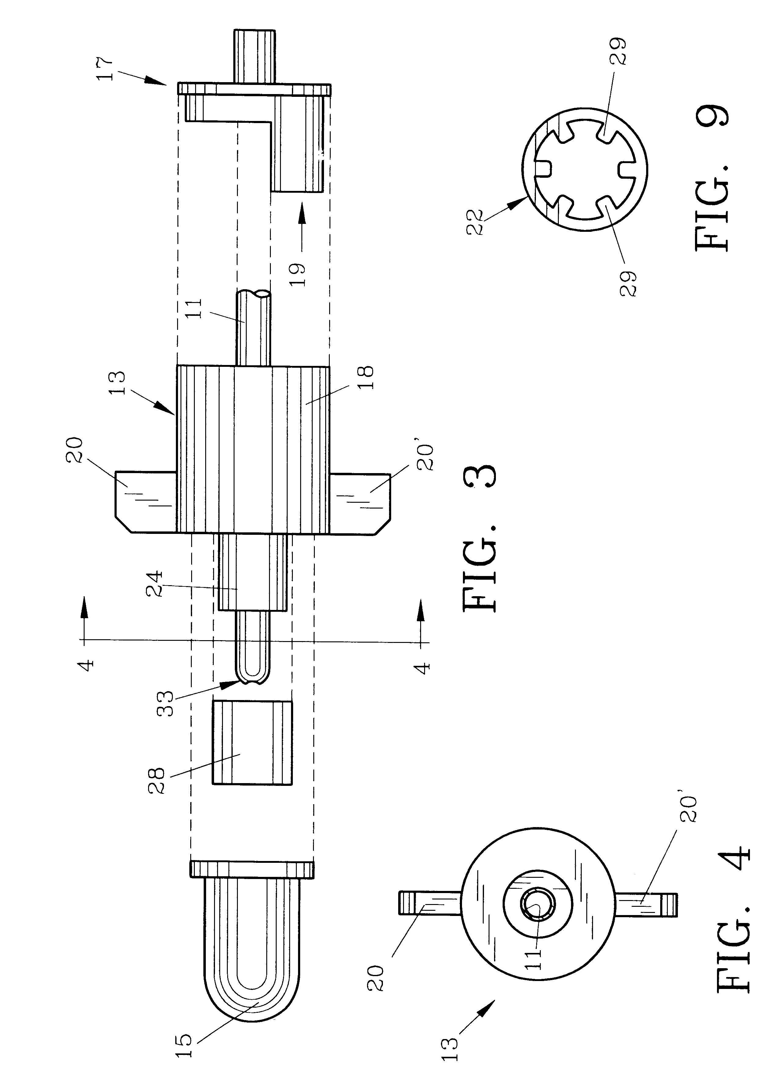
For a better understanding of the invention and its method of use, turning now to the drawings, FIG. 1 demonstrates preferred urethral catheter 10 contained within conventional transparent, polymeric package 12 having an application or front end 14 and a rear end 16. Catheter package 12 has front and back sides which are attached or sealed around the perimeter thereof to form a pocket for containing catheter 10. Catheter 10 includes catheter tube 11 which is formed of a conventional polymeric material and which passes through catheter movement control device 13. Cap 15 as seen in FIGS. 1 and 3 prevents contamination of tip 33 of catheter tube 11 as shown in FIG. 2. As would be understood, catheter tube 11 is manually manipulated into the urethra from package 12, outwardly through opening 26 in package 12 which is sealed around fitting 24.

In FIG. 3, partial catheter tube 11 is shown in preferred movement control device 13, with rear section 17 exploded therefrom. Rear section 17 enga...


PUM


Abstract

A catheter movement control device is presented having therein a resilient biasing member and a tube gripper which mount on a catheter tube. The biasing member and tube gripper are contained within a housing having a shoulder proximate the catheter tube. As the catheter tube is free to move in a forward direction through the housing, upon attempted rearward movement the biasing member engages the tube gripper causing it to pivot against a shoulder within the housing. Upon pivoting the tube gripper tightly engages the catheter tube preventing any further rearward movement of the catheter tube.

Description

The invention herein pertains to packaged catheters and particularly to control devices for limiting or controlling the extension of the catheter tube into and from the package.DESCRIPTION OF THE PRIOR ARTAND OBJECTIVES OF THE INVENTIONVarious devices have been conceived in the past to limit or control the movement of catheter tubes into and out of its surrounding package to stop or retard the catheter tube movement. As such catheters have lubricants applied, it is often difficult to control the insertion of the catheter tube which is formed from a lightweight, flexible, polymeric material. Insertion techniques vary and the personnel involved must be aware that an obstruction encountered, in for example the urethral tract, must be recognized and precautionary steps taken. Otherwise, forcing the catheter tube into or through an obstruction may cause significant discomfort, the creation of false passages which may become infected, or may result in severe (or fatal) injury to the patie...

Claims


Application Information

Patent Timeline
Patent Type & Authority Patents(United States)
IPC IPC(8): A61M25/01A61M25/00
CPCA61M25/0113A61M25/002A61M2210/1089
Inventor GENESE, JOSEPH N.
Owner MEDICAL TECH OF GEORGIA
Why Eureka
Try Eureka