Circuit and busboard connection for an electrical connection box

a technology of electrical connection box and circuit, which is applied in the direction of connection contact material, connection device connection, contact member penetrating/cutting insulation/cable strand, etc., can solve the problems of poor utilization efficiency of space used in arranging the bus-bars and increasing costs

Inactive Publication Date: 2002-06-25
AUTONETWORKS TECH LTD +2
View PDF5 Cites 21 Cited by
  • Summary
  • Abstract
  • Description
  • Claims
  • Application Information

AI Technical Summary

Benefits of technology

As the lead wires are pressure-welded to the respective pressure-contact knife-edges passed through the through-hole provided in the electronic circuit board in this circuit forming method and the circuit connection structure, the space for use in fitting the female terminals to the edge portion of the board in the prior art can be dispensed with, which results in making it possible to reduce the size of the electronic circuit board. Moreover, the pressure-contact knife-edges are directly pressure-welded to the respective lead wires, so that female terminals and the connector housing necessitated in the prior art can be omitted, which results in reducing the number of parts.
With this arrangement, as any number of pressure-contact knife-edges can freely be provided to the end portion or mid position of the bus-bar, the utilization efficiency of the space for use in disposing the bus-bars becomes improvable thereby.

Problems solved by technology

However, there have been the following problems concerning the connection structure of the bus-bar in the conventional electrical connection box.
Moreover, as a space for use in fitting up the female terminals 108 becomes necessary and this results in a large-sized electronic circuit board 104, thus increasing the cost.
Consequently, the utilization efficiency of the space for used in arranging the bus-bars has been poor.

Method used


Image

  • Circuit and busboard connection for an electrical connection box
  • Circuit and busboard connection for an electrical connection box
  • Circuit and busboard connection for an electrical connection box

Examples


Embodiment Construction

An embodiment of the present invention will now be described concretely.

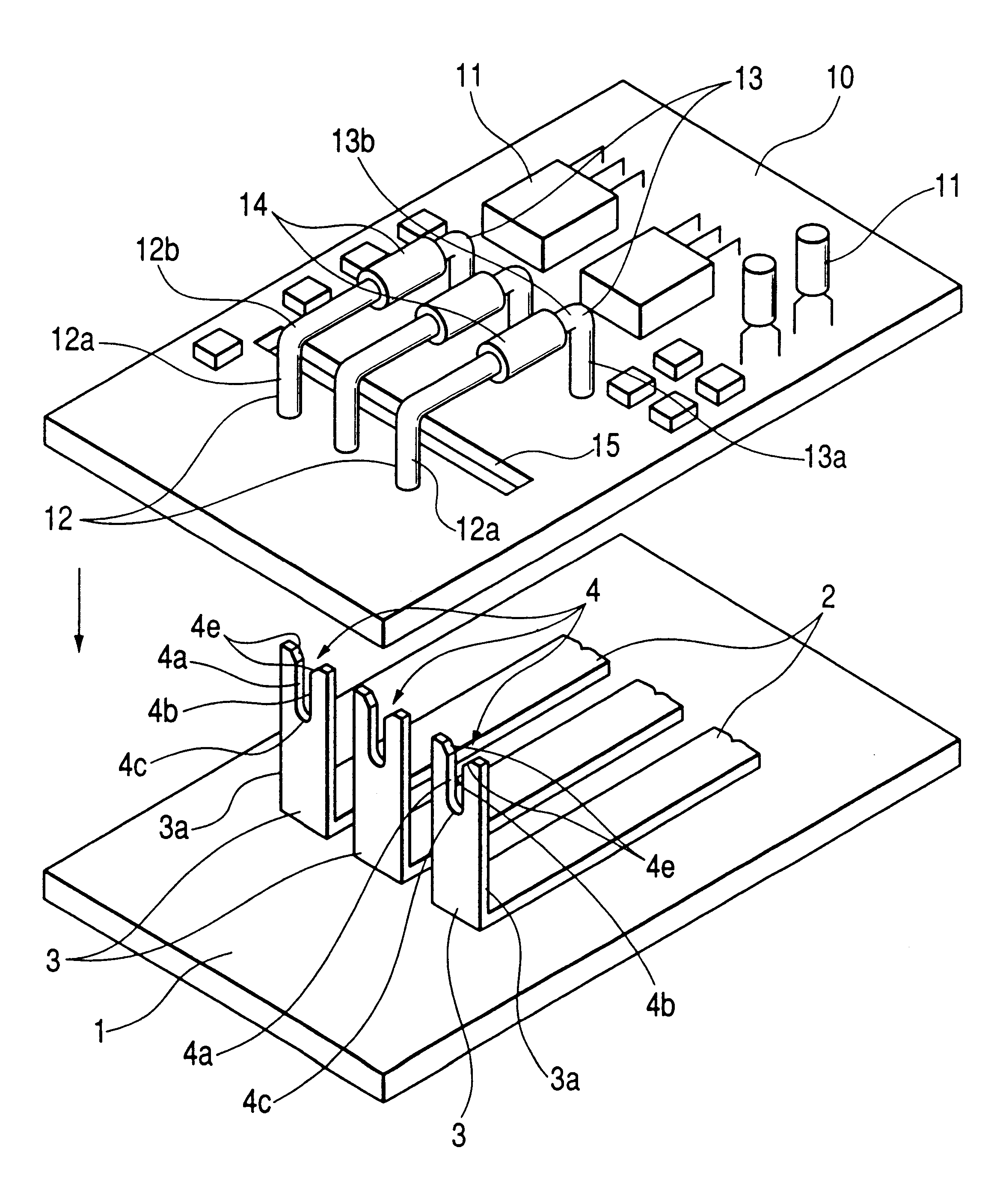
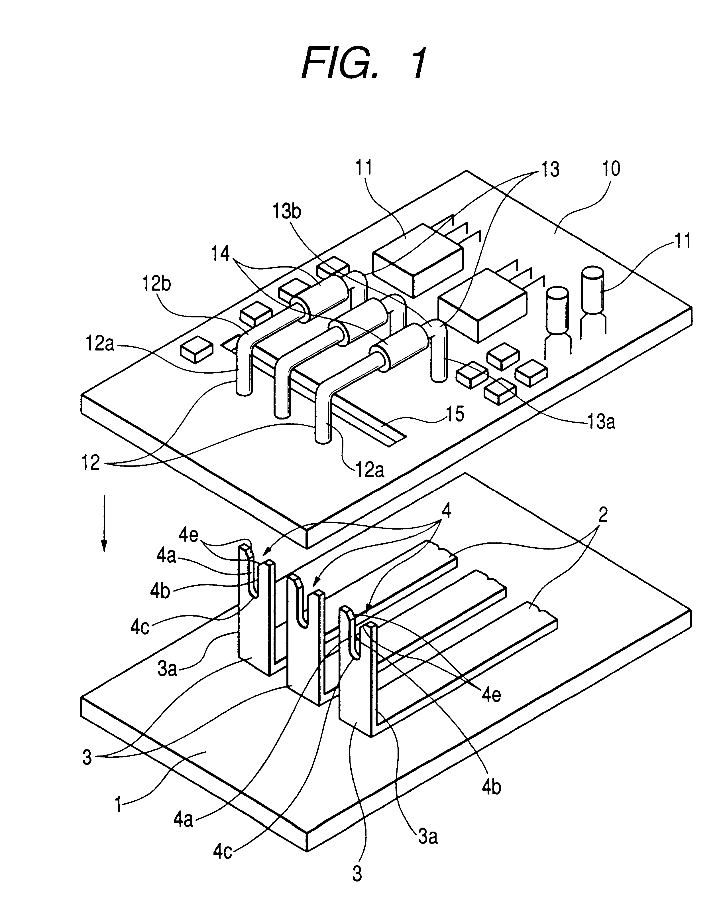
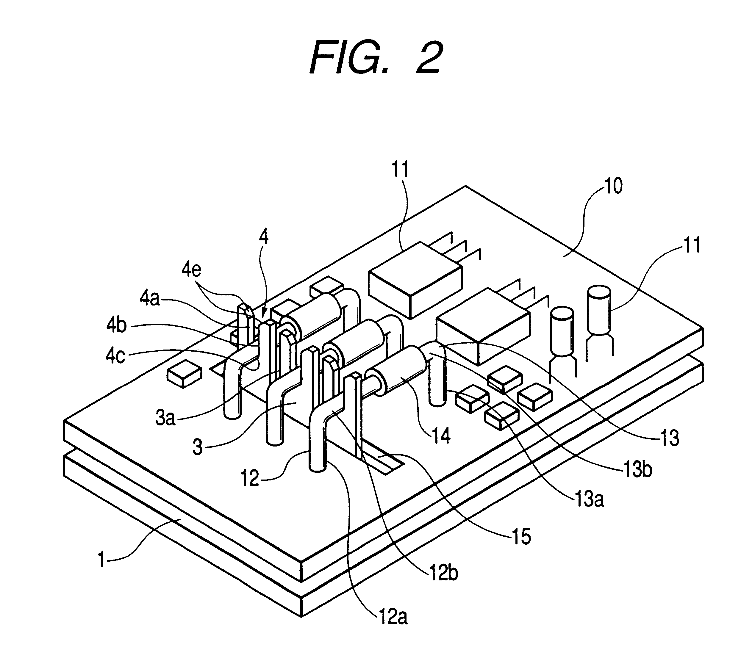
FIG. 1 is an exploded perspective view of a circuit connection structure in an electrical connection box embodying the invention; and FIG. 2 is a perspective view of the circuit connection structure.

The circuit connection structure is retained in a space formed between a lower case portion and an upper case portion (these being not shown) constituting the electrical connection box, an insulating board 1 being provided on the lower side and an electronic circuit board 10 being provided on the upper side.

A plurality of bus-bars 2, three of them in the example of FIG. 1, are arranged side by side on the surface of and in the width direction of the insulating board 1, and the edge portion of each bus-bar 2 is made an upright pressure-contact knife-edge 3. The pressure-contact knife-edge 3 has a slot 4, and a knife edge is formed on both vertical edge faces 4a and 4b of the slot 4 and on an arcuate edge face 4c there...


PUM


Abstract

A circuit connection structure comprises an electronic circuit board 10 having a through-hole 15, the electronic circuit board 10 being provided with lead wires 12 or electric wires of electronic parts 14 in a manner straddling the through-hole 15, and an insulating board 1 provided with bus-bars 2 having upright pressure-contact knife-edges 3 electrically connected to the lead wires 12 or electric wires. The electronic circuit board 10 and the insulating board 1 are stacked up by relatively moving both the boards close to each other in such a condition that the pressure-contact knife-edges are passing through the through-hole, whereby the lead wires 12 or electric wires are pressure-welded to the respective pressure-contact knife-edges 3.

Description

1. Field of the InventionThe present invention relates to a circuit forming method and a circuit connection structure in an electrical connection box for use in a vehicle, for example.2. Description of the Related ArtIn an electrical connection box of the sort mentioned above, an electronic circuit board 104 provided with electronic parts 103 between a lower case portion 101 and an upper case portion 102 constituting the electrical connection box, and an insulating board 106 provided with bus-bars 105 are generally housed in a laminated form as shown in FIG. 5.The electrical connection of the electronic parts 103 to the bus-bars 105 is accomplished by fitting a connector housing 107 retaining female terminals 108 to an edge portion of an electronic circuit board 104 and stacking the electronic circuit board 104 in this state on top of the insulating board 106 thereby to fit bus-bar tabs (male terminals) 105a with the bus-bars 105 in an upright condition into the respective female te...

Claims


Application Information

Patent Timeline
Patent Type & Authority Patents(United States)
IPC IPC(8): H01R13/502H01R4/24H01R13/504H01R4/02H05K1/02H05K1/14H05K3/20H01R4/58H02G3/16
CPCH01R4/021H01R4/242H01R13/504H05K1/0263H05K1/144Y10S439/949H05K2201/09063H05K2201/10272H05K2201/1053H05K2201/10651H05K3/202
Inventor ONIZUKA, TAKAHIRO
Owner AUTONETWORKS TECH LTD
Why Eureka
Try Eureka