Variable length code decoding device, digital broadcast receiving apparatus, and DVD reproducing apparatus

a technology of code decoding and digital broadcasting, applied in the direction of code conversion, electrical equipment, television systems, etc., can solve the problems of length code decoding device, increase in cost and power consumption of the system, and decrease in the processing speed of the overall system

Inactive Publication Date: 2002-07-02
SOVEREIGN PEAK VENTURES LLC
View PDF10 Cites 52 Cited by
  • Summary
  • Abstract
  • Description
  • Claims
  • Application Information

AI Technical Summary

Benefits of technology

With the above construction, the variable length code decoding device extracts two codewords from a compressed code stream and decodes them in parallel, with it being possible to increase the number of variable length codewords which can be decoded in a fixed time period.
With the above construction, a compressed code stream includes coded control information elements obtained by respectively coding control information elements of at least two different types. Two coded control information elements are extracted from this compressed code stream and are entropy decoded in parallel to reconstruct original control information elements, with it being possible to increase the number of variable length codewords which can be decoded in a fixed time period.

Problems solved by technology

However, this variable length code decoding device has the following problem.
Since variable length codewords are extracted and decoded one at a time, it takes long time to decode all of the codewords, which causes decreases in processing speed of the overall system.
Although such decreases in processing speed could be avoided by increasing the system's operating frequency, this will incur increases in cost and power consumption of the system.

Method used


Image

  • Variable length code decoding device, digital broadcast receiving apparatus, and DVD reproducing apparatus
  • Variable length code decoding device, digital broadcast receiving apparatus, and DVD reproducing apparatus
  • Variable length code decoding device, digital broadcast receiving apparatus, and DVD reproducing apparatus

Examples


first embodiment

1. First Embodiment

The following is a description of a variable length code decoding device 10 according to the first embodiment of the invention.

1.1. Construction of the Variable Length Code Decoding Device 10

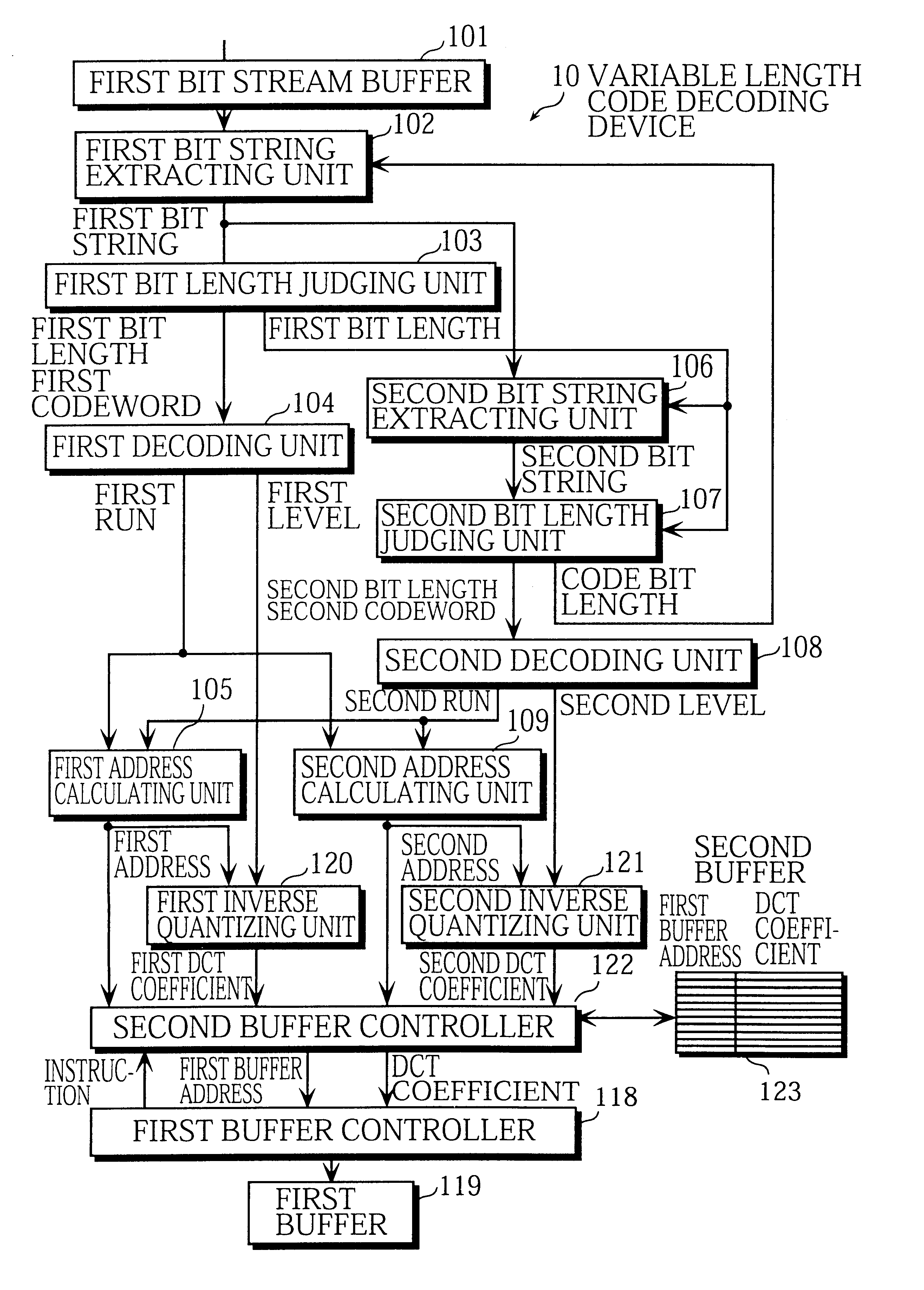
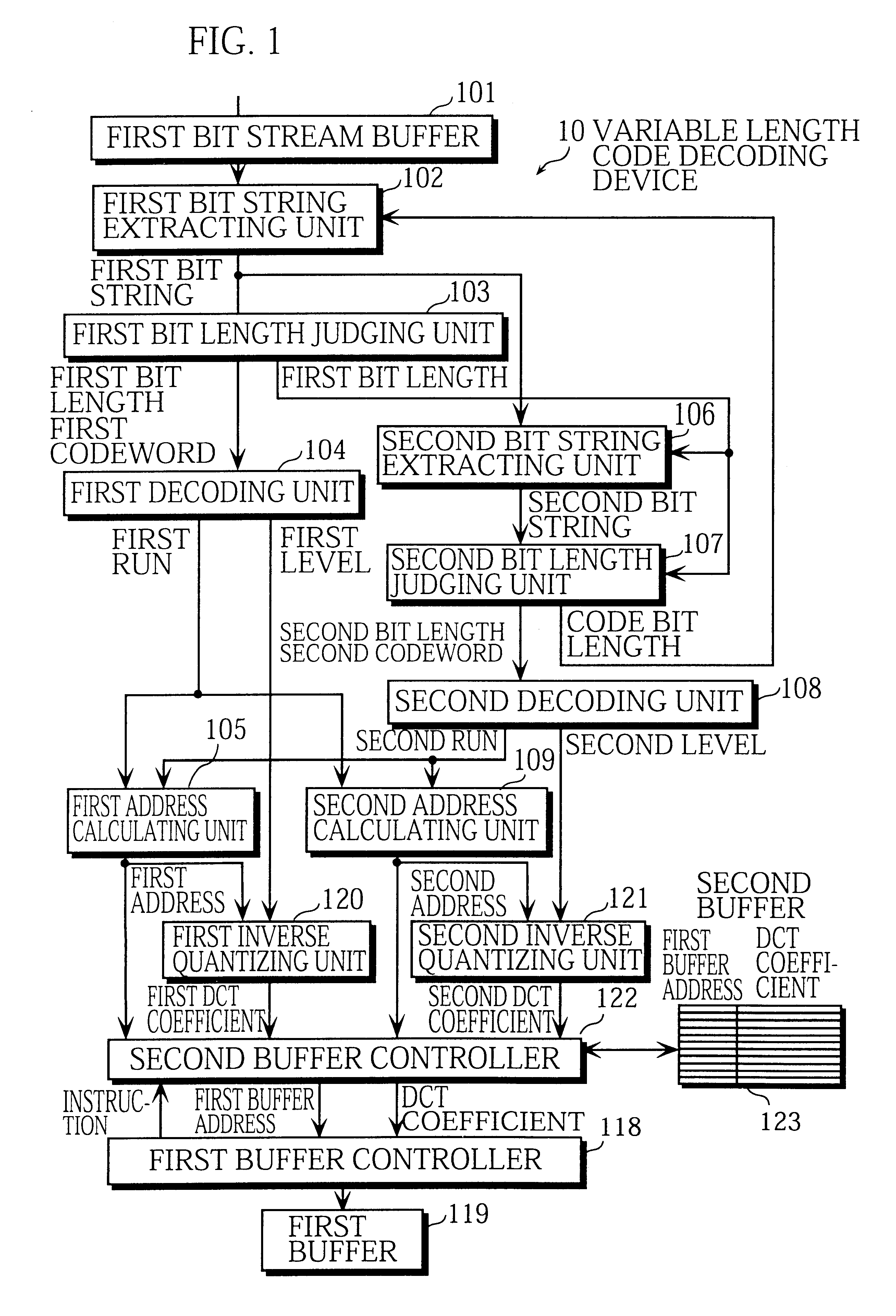
FIG. 1 is a block diagram showing the construction of the variable length code decoding device 10.

The variable length code decoding device 10 is roughly made up of a first bit stream buffer 101, a first bit string extracting unit 102, a first bit length judging unit 103, a first decoding unit 104, a first address calculating unit 105, a second bit string extracting unit 106, a second bit length judging unit 107, a second decoding unit 108, a second address calculating unit 109, a first buffer controller 118, a first buffer 119, a first inverse quantizing unit 120, a second inverse quantizing unit 121, a second buffer controller 122, and a second buffer 123.

1.1.1. First Bit Stream Buffer 101

The first bit stream buffer 101 is connected to an optical disk device and repeatedly re...

second embodiment

2. Second Embodiment

The following is a description of a variable length code decoding device 20 according to the second embodiment of the invention.

2.1. Construction of the Variable Length Code Decoding Device 20

FIGS. 15A, 15B, and 15C are block diagrams which together 1t show the construction of the variable length code decoding device 20.

The variable length code decoding device 20 includes a first bit stream buffer 101, a first bit string extracting unit 102, a first bit length judging unit 103, a first decoding unit 104, a first address calculating unit 105, a second bit string extracting unit 106, a second bit length judging unit 107, a second decoding unit 108, a second address calculating unit 109, a first buffer controller 118, a first buffer 119, a first inverse quantizing unit 120, a second inverse quantizing unit 121, a second buffer controller 122, a second buffer 123, a second bit stream buffer 110, a first bit length selecting unit 111, a bit string selecting unit 112, ...

third embodiment

3. Third Embodiment

The following is a description of a variable length code decoding device 30 according to the third embodiment of the invention.

3.1. Construction of the Variable Length Code Decoding Device 30

FIG. 18 is a block diagram showing the construction of the variable length code decoding device 30.

The variable length code decoding device 30 includes a first bit stream buffer 101, a first bit string extracting unit 102, a first bit length judging unit 103, a first decoding unit 140, a first address calculating unit 105, a second address calculating unit 109, a first buffer controller 118, a first buffer 119, a first inverse quantizing unit 120, a second inverse quantizing unit 121, a second buffer controller 122, and a second buffer 123.

Construction elements which are labeled by the same reference numerals are similar to those in the variable length code decoding device 10. The following explanation will focus on the newly added construction elements and, for the constructi...


PUM


Abstract

A first bit string extracting unit extracts a first bit string. A first bit length judging unit detects a first codeword from the first bit string. A first decoding unit generates a first run-level pair from the first codeword. A second bit string extracting unit extracts a second bit string. A second bit length judging unit detects a second codeword from the second bit string. A second decoding unit generates a second run-level pair from the second codeword. A first inverse quantizing unit inverse quantizes the first level to obtain a DCT coefficient. A second inverse quantizing unit inverse quantizes the second level to obtain a DCT coefficient. A second buffer controller writes the DCT coefficients and their first buffer addresses into a second buffer. A first buffer controller reads the DCT coefficients and the first buffer addresses from the second buffer and writes the DCT coefficients into a first buffer at the respective first buffer addresses.

Description

This application is based on an application No. H11-162113 filed in Japan, the content of which is hereby incorporated by reference.1. Field of the InventionThe present invention relates to a variable length code decoding device, digital broadcast receiving apparatus, and DVD reproducing apparatus for decoding a compressed code stream into original signals.2. Description of the Prior ArtTechnology for efficiently compressing and encoding images, represented by MPEG (Moving Picture Experts Group), has been increasingly explored in recent years.FIG. 27 is a block diagram showing a conventional variable length code decoding device for decoding variable length codewords. In the figure, a bit stream buffer 1001 acquires a bit stream of an encoded moving image from an outside source and retains it. A bit string extracting unit 1002 extracts a bit string as long as the maximum variable length from the beginning of the bit stream in the bit stream buffer 1001, and outputs the extracted bit ...

Claims


Application Information

Patent Timeline
Patent Type & Authority Patents(United States)
IPC IPC(8): H04N7/50H04N7/26
CPCH04N19/61H04N19/91H04N19/436
Inventor NISHIDA, HIDESHIYOSHIOKA, KOSUKEKIYOHARA, TOKUZO
Owner SOVEREIGN PEAK VENTURES LLC
Why Eureka
Try Eureka