Point-of-sale terminal adapter

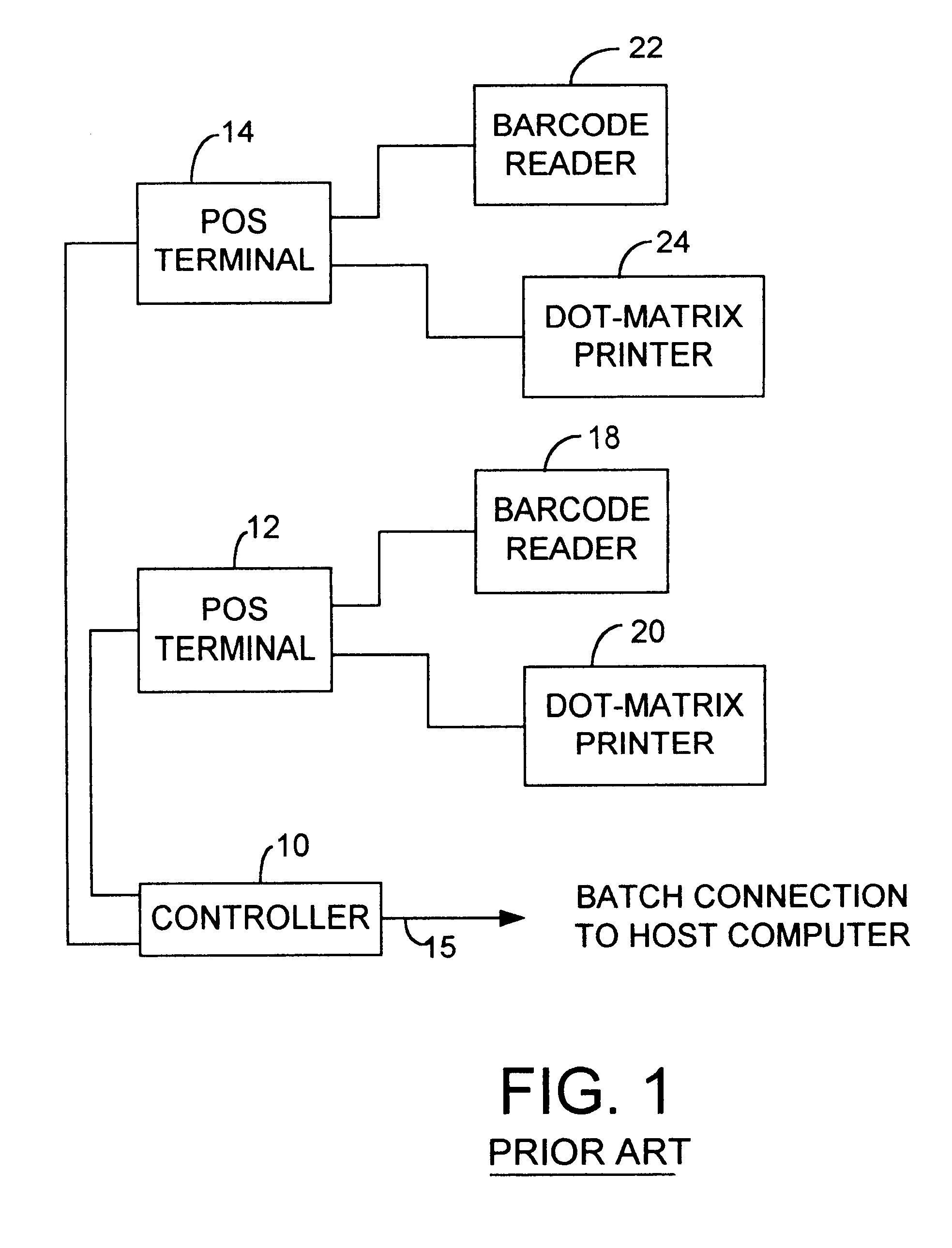
a terminal adapter and point-of-sale technology, applied in the direction of instruments, electric digital data processing, cash registers, etc., can solve the problems of limited compatibility between pos terminals and controllers, a new pos system, and a variety of new components

Inactive Publication Date: 2002-07-02
R2 CORP
View PDF15 Cites 88 Cited by
  • Summary
  • Abstract
  • Description
  • Claims
  • Application Information

AI Technical Summary

Benefits of technology

The present invention is, according to one aspect, a method of adapting a computer terminal for connection to at least one peripheral device. The computer terminal is capable of communicating signals with external devices in a prescribed manner, which must be emulated to the computer terminal to ensure proper operation. An adapter is communicatively coupled to the computer terminal and to the at least one peripheral device. The computer terminal is configured to transmit data and commands to the adapter in the manner prescribed for communication with external devices. The adapter is configured to detect computer terminal signals and transform selected patterns of the computer terminal signals into instruction and

Problems solved by technology

New cash register terminals and controllers have been introduced that have significant differences from earlier terminals, and many peripherals are proprietary and therefore not designed to operate with older terminals or with terminals manufactured by competing companies.
In addition, some applications of POS systems require memory or other capabilities that cannot be provided in the older terminals or the competing terminals.
To simply purchase a completely new POS system, with a variety of new components, is an extremely expensive undertaking that requires a retailer to effectively scrap the prior system, which is undesirable because of the sizable investment that the retailer has already made in that s

Method used


Image

  • Point-of-sale terminal adapter
  • Point-of-sale terminal adapter
  • Point-of-sale terminal adapter

Examples


Embodiment Construction

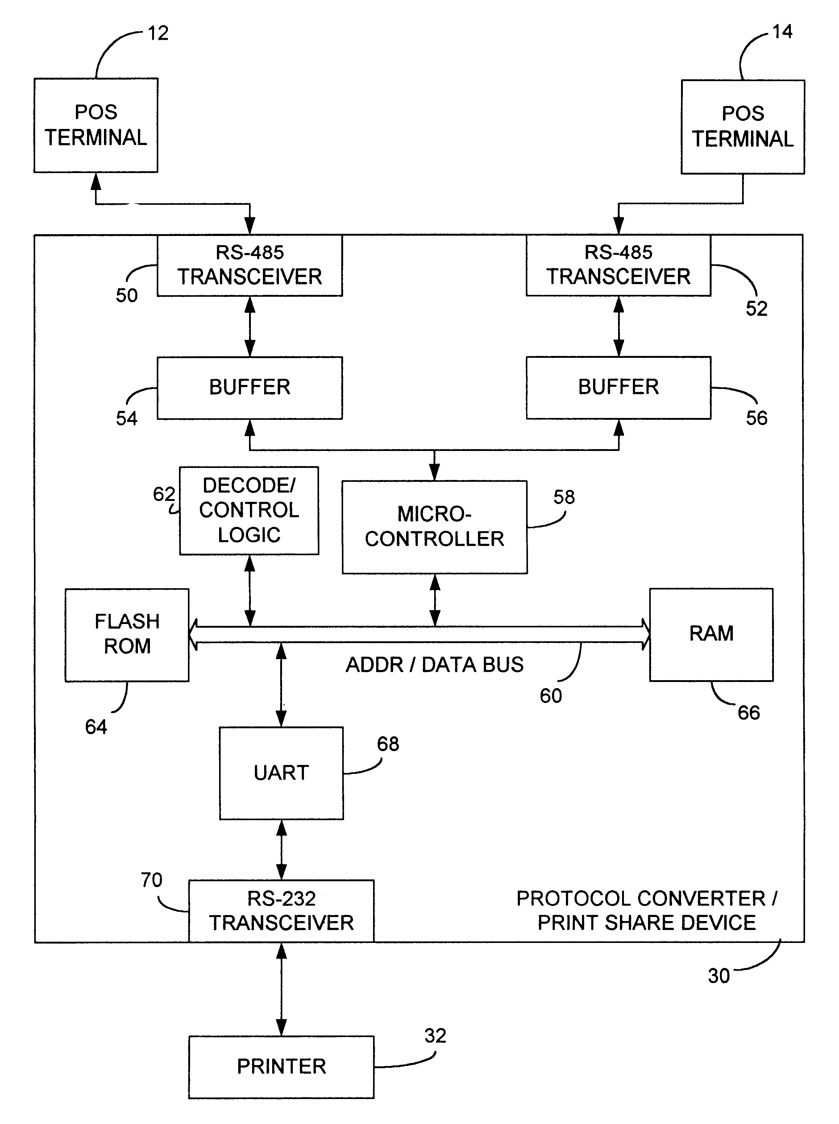
Exemplary Record Format for Protocol Conversion

A-1 Physical Characteristics

Data is transmitted using a baud rate (which is configurable) of 38,400 with 8 data bits, no parity, and 1 stop bit (38400,8,N,1).

A-2 Record Format

All characters contained in the record are within the printable ASCII character set (0.times.20-0.times.7e). The complete record is shown below.

The different fields are discussed below followed by detailed descriptions for each device.

A-2.1 Record Fields

A-2.1.1 Device Indicator

The first character of the record indicates either a device or error condition. Below are examples of such codes.

A-2.1.2 Status Data

The second field of the data record qualifies device data, if needed. This field is optional but does have a predefined fixed length for each device.

A-2.1.3 Data Separator

The data separator is an ASCII colon (`:`) used to easily distinguish device ID and status from device data.

A-2.1.4 Device Data

Device data is the data that has been either transmitted or receive...


PUM


Abstract

A device and method for adapting a computer terminal for connection to at least one external device communicatively couples an adapter to the computer terminal and to the at least one external device. The computer terminal is configured to transmit data and commands to the adapter in a manner prescribed by the computer terminal for communication with external devices. The adapter is configured to detect computer terminal signals and transform selected patterns of the computer terminal signals into instructions and information having a predetermined format for operating the at least one external device. The data and commands transmitted from the computer terminal are interpreted and transformed into instructions and information in a predetermined format for operating the at least one external device. Signals are transmitted from the adapter to the computer terminal according to the manner of communication prescribed by the computer terminal, and the instructions and information for operating the at least one external device are transmitted to the at least one external device.

Description

The present invention relates to a system for expanding the compatibility of a point-of-sale computer terminal. More particularly, the present invention relates to a device and method of coupling to data in a point-of-sale computer terminal and interpreting and converting that data for use by devices external to the terminal, including devices with which the terminal was not designed to operate.Point-of-sale (POS) systems have become extremely common for transacting business between commercial retailers and consumers. Essentially, a POS system comprises one or more controllers connected to a plurality of POS computer terminals, such as cash register terminals. The cash register terminals are in turn connected to one or more peripheral devices that operate with the terminals. For example, a controller may be connected to three cash register terminals, and each cash register terminal may be connected to a printer and a bar code reader. Therefore, in operation, a consumer may present a...

Claims


Application Information

Patent Timeline
IPC IPC(8): G07G1/14
CPCG07G1/14
Inventor FRY, SR., THOMAS D.HARRIS, JR., KYLE H.PRATHER, EDWARD C.PRUBAN, JR., RAYMOND P.
Owner R2 CORP
Why Eureka
Try Eureka