
Silenced blowing nozzle

Inactive Publication Date: 2002-07-09
SILVENT
View PDF6 Cites 18 Cited by
  • Summary
  • Abstract
  • Description
  • Claims
  • Application Information

AI Technical Summary

Benefits of technology

The object of the present invention is to offer an efficient blowing nozzle with which a significantly higher and / or quieter blowing force can be achieved for a given frontal area than with corresponding known nozzles.
To achieve the desired blowing force, the nozzle according to the invention comprises at least one first discharge opening in a central part of the nozzle, where the first discharge opening is diverging, suitably formed as a Laval nozzle, to give the discharging gas, normally air, supersonic velocity at the pressure prevailing most immediately behind the discharge. For a correctly formed Laval nozzle, the pressure of the air / gas is converted completely to kinetic energy, which implies that the gas stream does not expand sideways after it has left the nozzle, as is the case for conventional nozzles, where the expansion creates intense noise. A powerful noise occurs nevertheless when gas flows with supersonic velocity out of a correctly dimensioned Laval nozzle. This is assumed caused by violent turbulence arising in the boundary zone between the gas / air stream which rushes forward with a very high velocity, and the surrounding air. The invention aims to solve this problem. According to the invention, the vortex formation in a gas exiting with supersonic velocity in a core stream near said first discharge opening, and therewith the generation of high frequency sound within the audible region, is suppressed in that the core stream is surrounded by a gas flow aimed in the direction of the core stream, which prevents or significantly reduces vortex formation of the core stream near said discharge opening, by which the initially mainly laminar character of the core stream is preserved to a large degree at least within a critical region near the discharge, where the velocity of the core stream is greatest.
Mechanically, the combination implies a nozzle with a very high degree of efficiency, as the surrounding gas flow causes insignificant slowing down of the velocity of the core stream in the critical region after the orifice by the surrounding stationary air, as most of the mechanical work in accelerating the stationary air in the direction of the core stream is carried out by the surrounding gas flow.
The second discharge openings, especially when these are arranged in the periphery of the nozzle, can be advantageously formed as thin slit openings which extend radially across the projected end area of the nozzle, perpendicular to the longitudinal axis thereof. To form a blowing nozzle with such slit-formed, radially oriented discharge openings in the periphery of the nozzle is known per se through e.g. EP 0 224 555 and the principle is practised in the 700-series of Silvent AB, see above, but has according to the invention at least two purposes in the nozzle. Firstly, the peripheral discharge openings act so that the blowing force reaches a high degree of efficiency even at large distances, secondly the gas stream flowing out through the peripheral openings and surrounding the central gas stream which flows out with supersonic velocity, muffles the otherwise very powerful sound which forms by interaction between the central gas stream with supersonic velocity and the surrounding air, by suppressing the turbulence of the core stream in a critical region. Thus the noise has, on trials done with blowing nozzles according to the invention and compared with a conventional nozzle in the paper industry, at a working pressure of 500 kPa, been reduced from 115 dB(A) for the conventional nozzle to 100 dB(A) for the new nozzle and this with maintained or amplified blowing force. This extraordinarily effective reduction in noise can be utilized for significantly improving the working conditions at existing compressed air equipment and / or for making new equipment significantly less expensive.

Problems solved by technology

A powerful noise occurs nevertheless when gas flows with supersonic velocity out of a correctly dimensioned Laval nozzle.

Method used


Image

  • Silenced blowing nozzle
  • Silenced blowing nozzle
  • Silenced blowing nozzle

Examples


Embodiment Construction

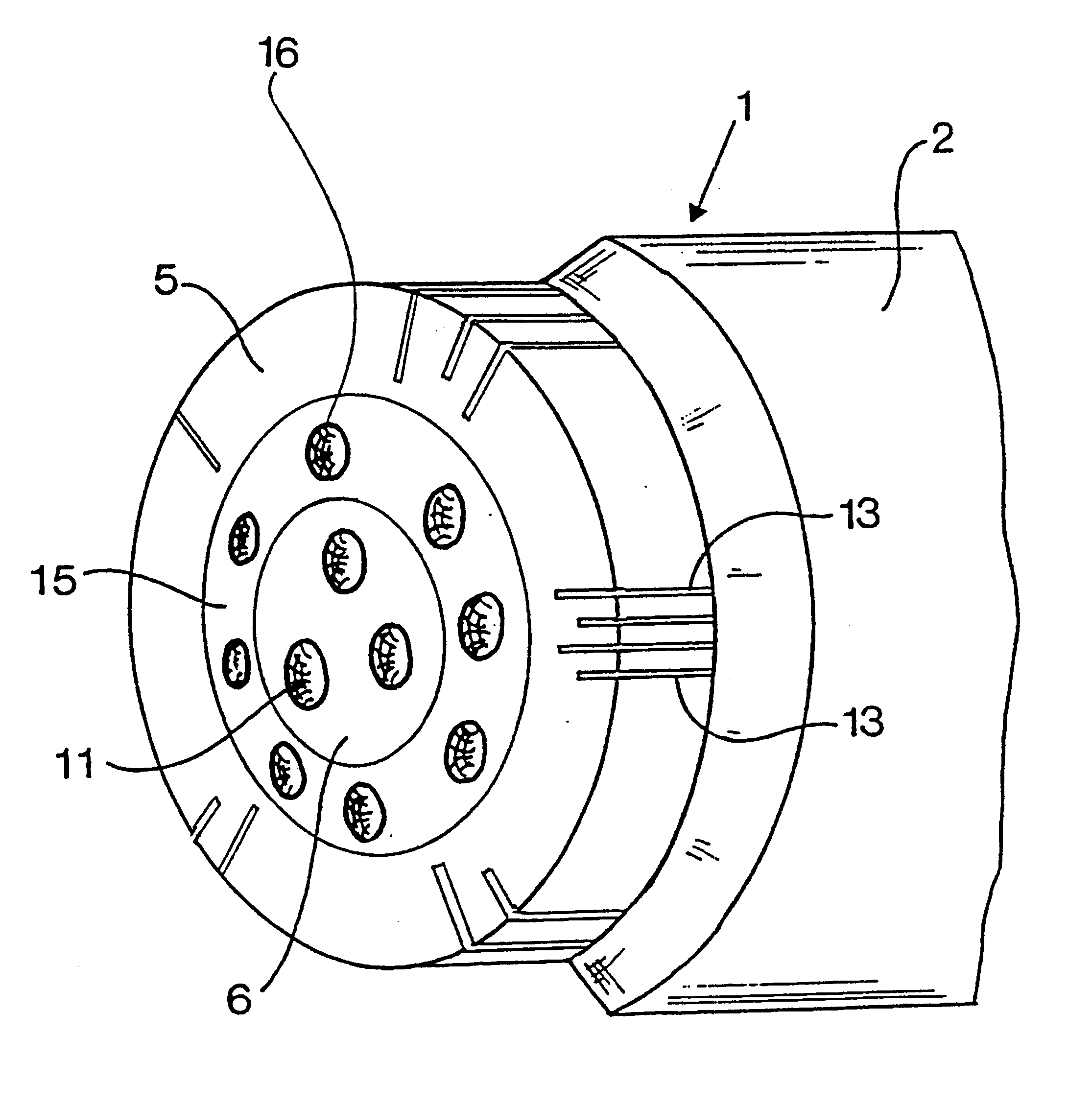
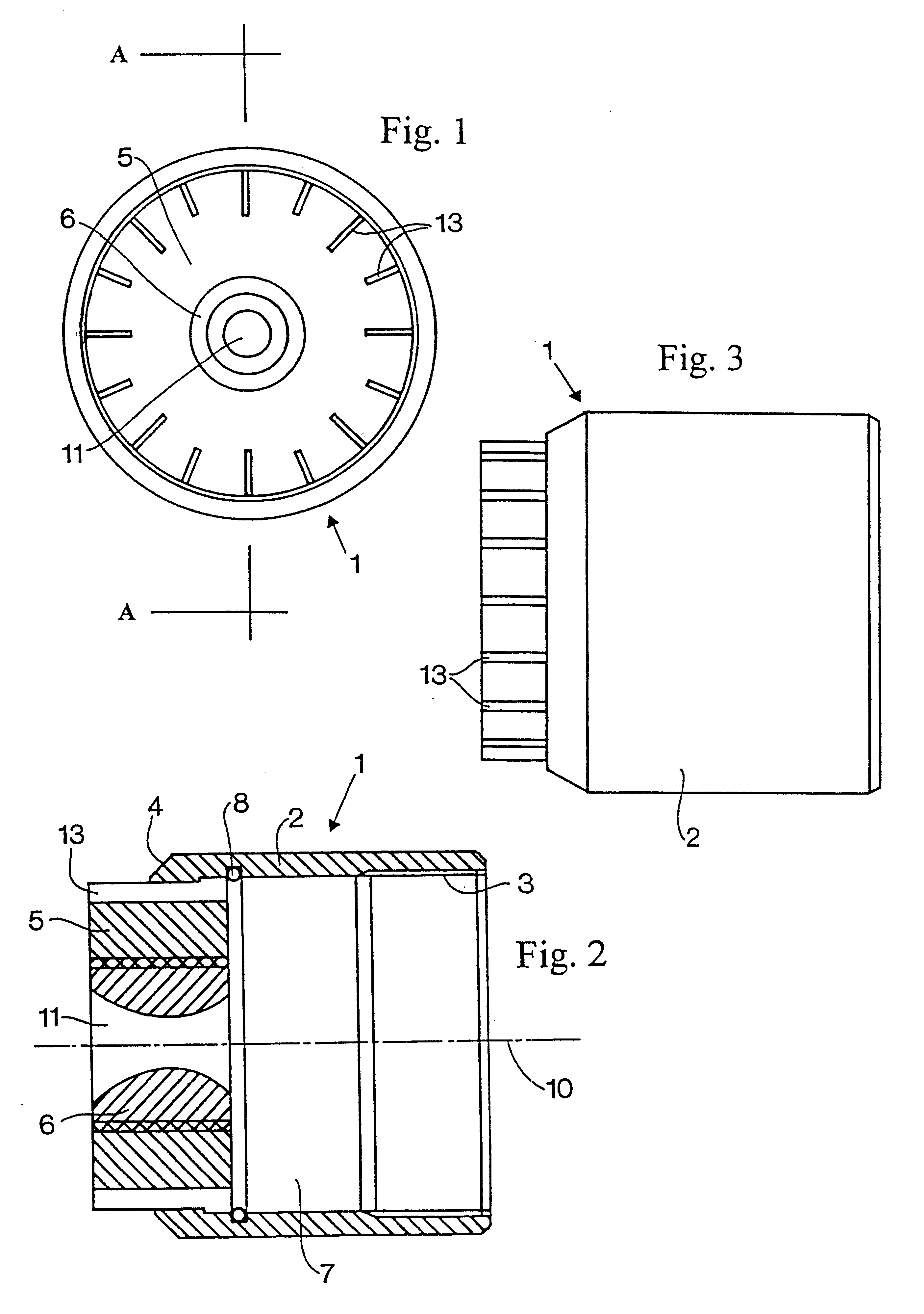
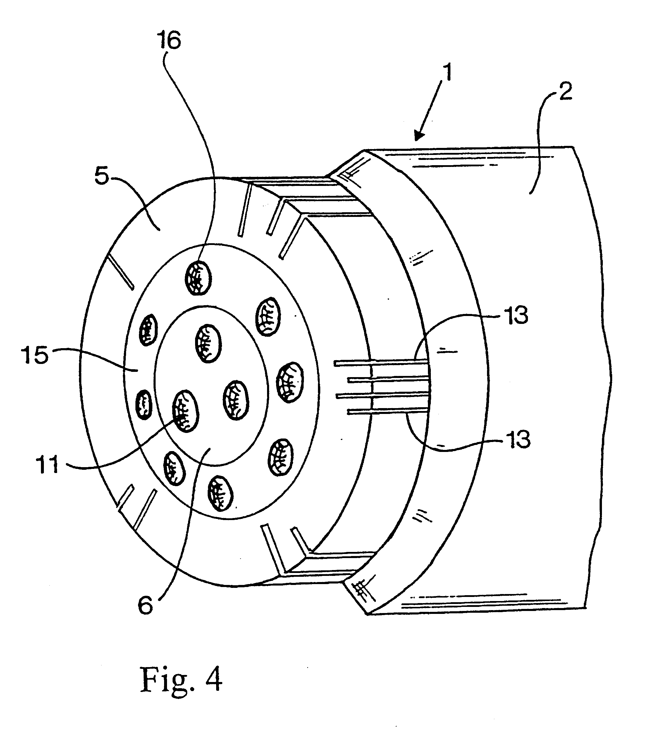
With reference first to FIGS. 1-3, a blowing nozzle is identified generally by the reference numeral 1. It consists of a tube-shaped casing 2 with internal threads 3 in a rear end as well as an outer and an inner nozzle body 5 respectively 6 in the front end of the casing, of which the front end part 4 is bevelled to a cone shape.

The casing 2 is connectable with the threads 3 to a compressed air line not shown, which connects the nozzle 1 with a compressed air source, so that an overpressure of at least 200 kPa can be maintained in a nozzle chamber 7 immediately behind the nozzle bodies 5 and 6. The outer nozzle body 5 is mounted by press fitting in the casing 2. It protrudes past the front part 4 of the casing and its rear end abuts against a clamp ring 8. The outer and central nozzle parts 5, 6 are embodied as matching screw and nut, of which the central nozzle part 6 is threaded into the outer nozzle part 5. It is perceived that this gives possibility for changing of the central ...


PUM


Abstract

The present invention relates to a silenced blowing nozzle for blowing of a static gas medium under overpressure, in particular air, having in a central part (6) of the nozzle at least one first discharge opening (11) embodied to generate a core stream of gas with supersonic velocity. The central part is surrounded by a more peripheral part (5) containing a number of second discharge openings (13) spaced from each other and from said first discharge opening(s), the said second discharge openings being embodied to generate a gas flow with lower velocity than the core stream, preferably a velocity equal to sonic velocity, which gas flow surrounds the core stream and has the same direction as said core stream.

Description

The present invention relates to a silenced blowing nozzle for emitting a gas medium, in particular air, under high overpressure.DESCRIPTION OF THE BACKGROUND ARTFor many years within the engineering industry, blowing nozzles of so-called "silent type" have been used, i.e. blowing nozzles which for a given blowing force are considerably quieter than corresponding standard blowing nozzles. Belonging to this group of blowing nozzles are tapered slot nozzles of type Silvent.RTM. 511 and 512, cupped hole nozzles of type Silvent.RTM. 208 and 209 and blowing nozzles with flat ends, type Silvent .RTM. 701-720. These blowing nozzles are used for low and moderate blowing forces and blowing distances. So-called "large blowers" are used where large blowing forces are required at long distances. Belonging to this group are aggregates consisting of a larger number of co-operating hole nozzles, which belong to the Silvent.RTM. 1100- and 1200-series of the same applicant. These tools are used for ...

Claims


Application Information

Patent Timeline
IPC IPC(8): B05B1/00D21G9/00D21G5/00
CPCB05B1/005D21G9/0063
Inventor ERIKSSON, GUNNAR
Owner SILVENT
Learn More