Modulated fibre bragg grating strain gauge assembly for absolute gauging of strain

a strain gauge and fibre bragg grating technology, applied in the direction of instruments, converting sensor output, photometry, etc., can solve the problems of increasing the weight and expense of the gauge, false or distorted readings, and the relative unsatisfactory use of conventional gauges on aircra

Inactive Publication Date: 2002-07-09
BAE SYSTEMS PLC
View PDF10 Cites 43 Cited by
  • Summary
  • Abstract
  • Description
  • Claims
  • Application Information

AI Technical Summary

Problems solved by technology

Conventional electrical strain gauges require a relatively large number of electrical lead outs which increases their weight and expense.
Additionally such conventional electrical strain gauges are subject to electromagnetic noise which can give rise to false or distorted readings.
This makes such conventional gauges relatively unsatisfactory for use on aircraft either as the retrofit assembly or as part of a composite panel assembly.
Moreover in an aircraft application the use of electrical cables means that they can be damaged by lightening strikes with consequent reduction in reliability and life of the strain gauge assembly.
However, the fibre optic sensors presently used for strain gauge monitoring, namely the fibre Fabry perot interferometer and the fibre Bragg grating, each have practical limitations associated therewith.
The fibre Fabry perot interferometer, although it achieves a high strain resolution and an excellent signal to noise ratio, is not an absolute gauge and it is difficult to multiplex a matrix of these devices over a fibre optic network.
The fibre Bragg grating can achieve absolute gauging of strain and is better suited to multiplexing than the fibre Fabry perot interferometer, but the signal to noise ratio is poor both as a result of the conventional broadband light source used, and because standard fibre Bragg gratings only reflect light over a narrow waveband.

Method used


Image

  • Modulated fibre bragg grating strain gauge assembly for absolute gauging of strain
  • Modulated fibre bragg grating strain gauge assembly for absolute gauging of strain
  • Modulated fibre bragg grating strain gauge assembly for absolute gauging of strain

Examples


first embodiment

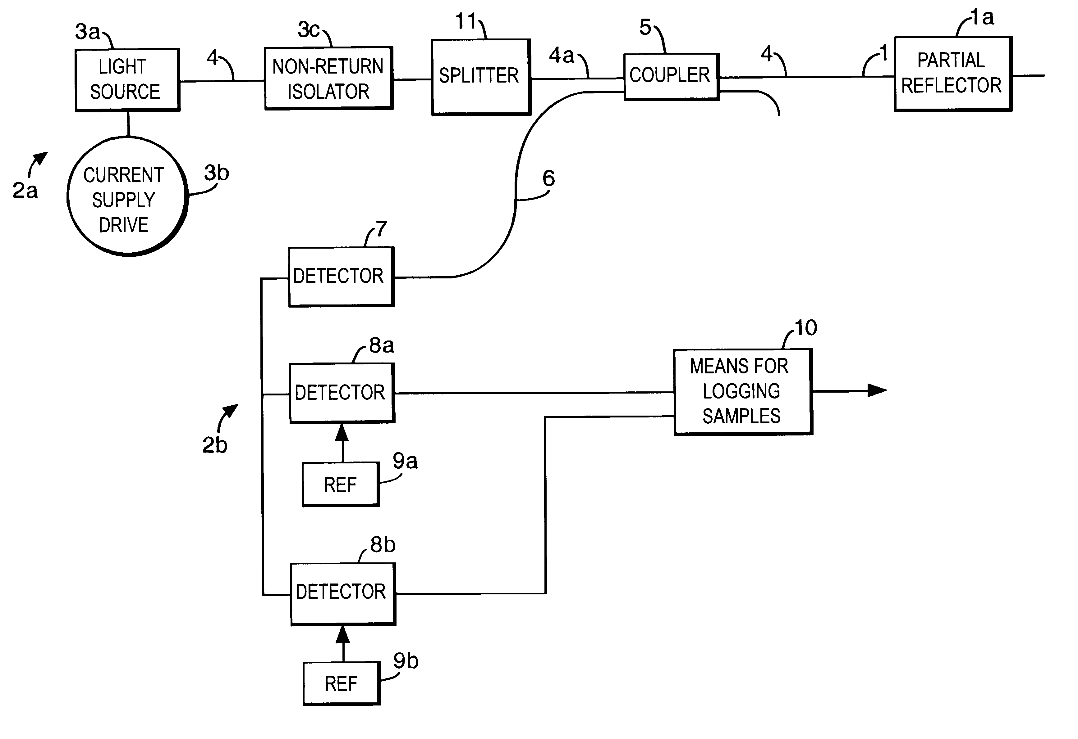
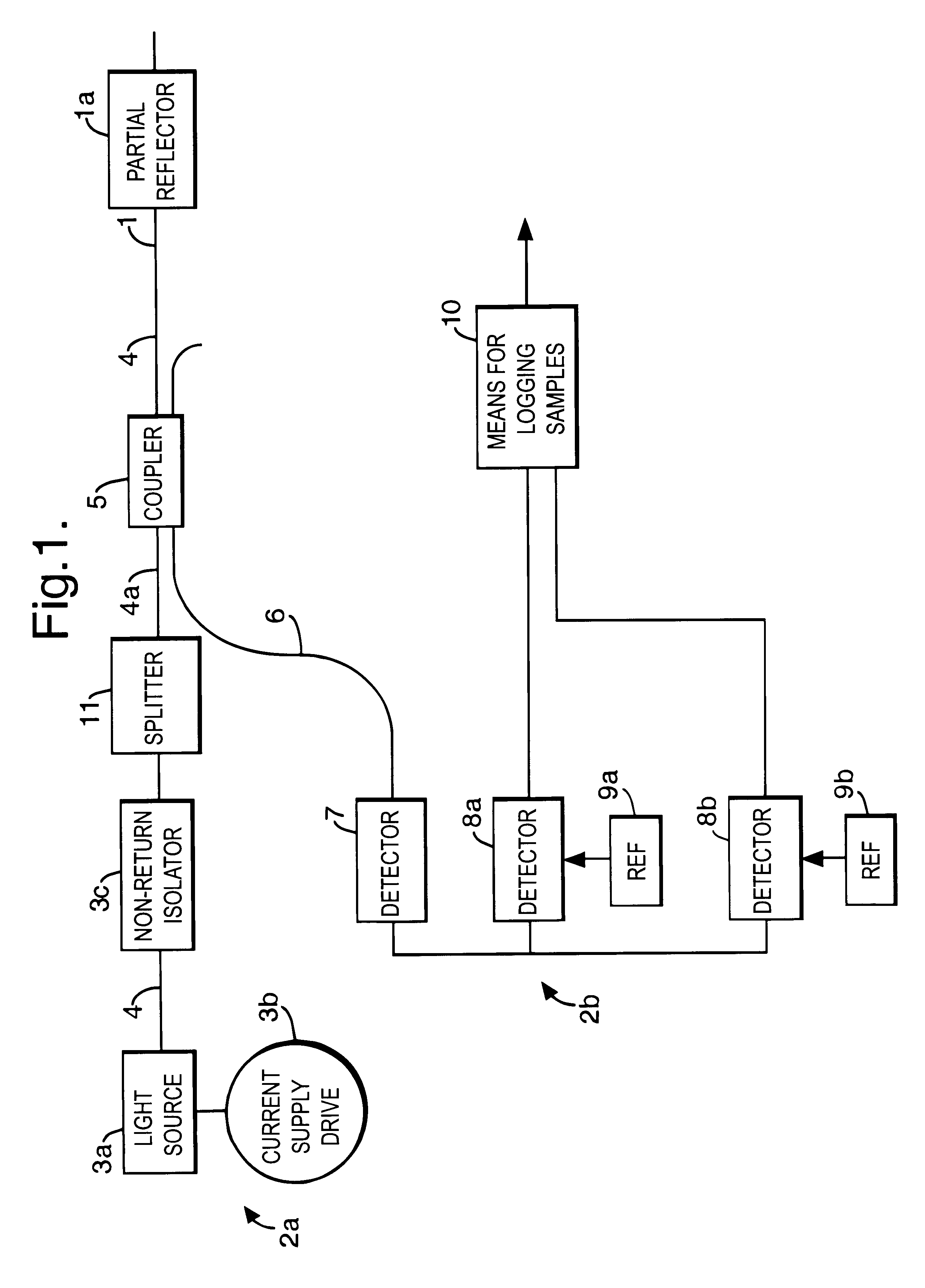
Thus a modulated fibre Bragg grating strain gauge assembly for absolute gauging of strain as shown schematically in FIG. 1 according to the present invention includes at least one sensor element 1 in the form of a length of optical fibre containing, along part its length, means for partially reflecting light 1a, and means 2a for generating and passing a beam of light with a spectral feature less than 0.1 nanometers in width into the at least one sensor element 1 where reflection takes place. This reflection is a substantially sinusoidal intensity variation in wavelength over a range of from 2 to 3 nanometers comprising at least two substantially sinusoidal periods, such that as the at least one sensor element sustains a change in length resulting from a strain thereon, the reflected intensity varies substantially sinusoidally along the at least two sinusoidal periods. FIG. 1 also shows means for receiving and processing the reflected light 2b to establish the light intensity values ...

second embodiment

The calibrating means corresponding to the present invention is shown in FIG. 12 and includes a series of five first calibration gratings 29a, 29b, 29c, 29d, 29e, each of which are locatable along one of the at least one sensor elements in the form of an optical fibre 29, and a series of five second calibration gratings 30a, 30b, 30c, 30d, 30e, each of which are locatable along one of the at least one sensor elements also in the form of an optical fibre 30. Each of the first and second calibration gratings are of a type made by a programmable ultra violet interference fabrication process, substantially as hereinbefore described in relation to each of the single Bragg gratings. The five first calibration gratings 29a, 29b, 29c, 29d, 29e are each unstrained and locatable in a controlled temperature environment, thereby providing temperature stabilised ratios of the intensity values (1f.sub.i :2f.sub.i).sub.T corresponding to each of the series of single Bragg gratings 1a, 1b, 1c, 1d, ...


PUM

PropertyMeasurementUnit
lengthaaaaaaaaaa
lengthaaaaaaaaaa
widthaaaaaaaaaa

Abstract

A modulated fibre Bragg grating strain gauge assembly for absolute gauging of strain including at least one sensor element (1) in the form of a length of optical fibre containing, along part its length, means for partially reflecting light (1a), means for generating and passing a beam of light (2a) with a spectral feature less than 0.1 nanometers in width into the at least one sensor element (1) where reflection takes place, which reflection is a substantially sinusoidal intensity variation in wavelength over a range of from 2 to 3 nanometers comprising at least two substantially sinusoidal periods such that as the at least one sensor element sustains a change in length resulting from a strain thereon, the reflected intensity varies substantially sinusoidally along the at least two sinusoidal periods, means for receiving and processing the reflected light (2b) to establish the light intensity values at one (1f) and two times (2f) a modulation frequency (1f) applied to the means for generating the beam of light (2a), and means to determine an absolute direction and magnitude of strain from a ratio of the intensity values 1f:2f.

Description

1. Field of the InventionThis invention relates to a modulated fibre Bragg grating strain gauge assembly suitable particularly, but not exclusively, for absolute gauging of strain.2. Discussion of Prior ArtConventional electrical strain gauges require a relatively large number of electrical lead outs which increases their weight and expense. Additionally such conventional electrical strain gauges are subject to electromagnetic noise which can give rise to false or distorted readings. This makes such conventional gauges relatively unsatisfactory for use on aircraft either as the retrofit assembly or as part of a composite panel assembly. Moreover in an aircraft application the use of electrical cables means that they can be damaged by lightening strikes with consequent reduction in reliability and life of the strain gauge assembly. Fibre optic strain gauges, such as is disclosed in patent application EP-840091-A2, offer particular advantages in airframe structures in terms of health ...

Claims


Application Information

Patent Timeline
Patent Type & Authority Patents(United States)
IPC IPC(8): G01D5/353G01L1/24G01D5/26G01B11/16
CPCG01D5/35316G01L1/246
Inventor MALVERN, ALANALLSOP, THOMASNEAL, RONALD
Owner BAE SYSTEMS PLC
Why Eureka
Try Eureka