
Device for RF control

a technology of rf electrodes and control devices, applied in the field of rf electrodes, can solve the problems of system normal instability, deterioration of the acceleration system, and drifting resonance frequency of the rf electrode system over time, and achieve the effect of high rf electrode voltag

Inactive Publication Date: 2002-07-09
GEMS PET SYST
View PDF8 Cites 94 Cited by
  • Summary
  • Abstract
  • Description
  • Claims
  • Application Information

AI Technical Summary

Benefits of technology

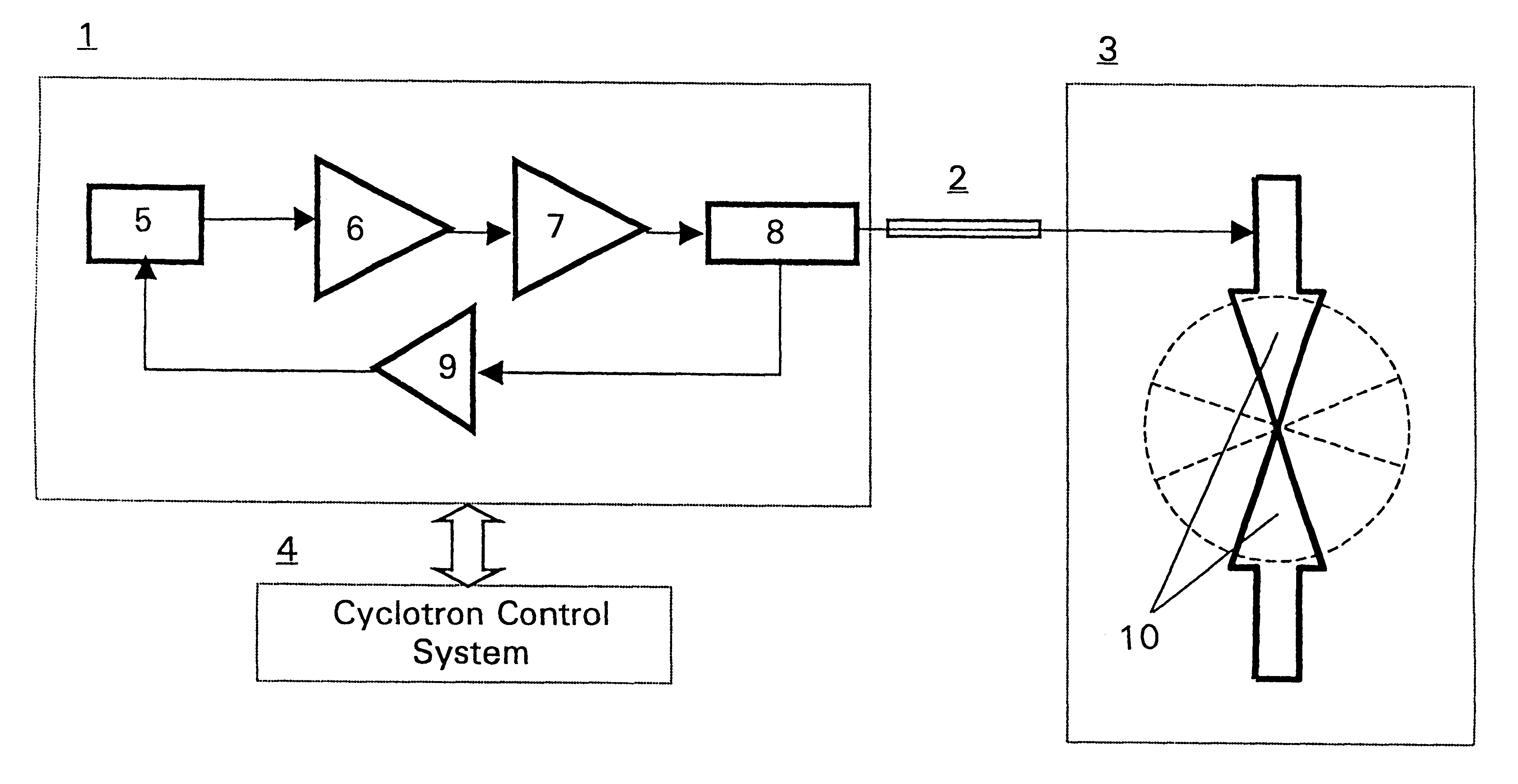
The present invention discloses a method and a system for obtaining a proper resonance of the RF electrodes when using a pre-set or predetermined stable frequency oscillator in a cyclotron accelerator without using mechanical tuning devices. In order to maintain a high RF electrode voltage during operation the RF electrode system resonance is monitored and the frequency of the stable frequency generator is controlled by a feedback system continuously monitoring the matching of the oscillator output frequency and the resonance frequency of the RF electrode system. Necessary small adjustments of the stable oscillator frequency to maintain a maximum matching to the resonance frequency of the RF electrode system are obtained by means of the feedback system to the stable oscillator. The feedback system relies on measured values obtained by a load phase sensor monitoring the output of the final RF power amplifier. A cyclotron control system in turn obtains the set and corrected oscillator frequency value and fine tunes further the magnetic field created in the accelerator device according to the frequency information obtained.

Problems solved by technology

However there is a problem in that the resonance frequency of the RF electrode system will drift over time due to temperature variations and other factors affecting its resonance frequency.
Such a drift of the resonance frequency means that the frequency of the applied high voltage oscillation no longer will correspond to the resonance of the RF electrodes in the accelerating system, and such a mismatch leads to a deteriorating function of the acceleration system.
Such a system will normally be rather unstable and requires a higher degree of operator attendance, which is not desirable for a handy system to be used for producing PET isotopes for instance at a hospital facility.
Besides, such a mechanical tuning system introduces a number of feeds through the vacuum casing of the accelerator, except for the maintenance problems which may arise regarding the electrical motors used as well as the mechanical tuning system itself.

Method used


Image

  • Device for RF control
  • Device for RF control

Examples


Embodiment Construction

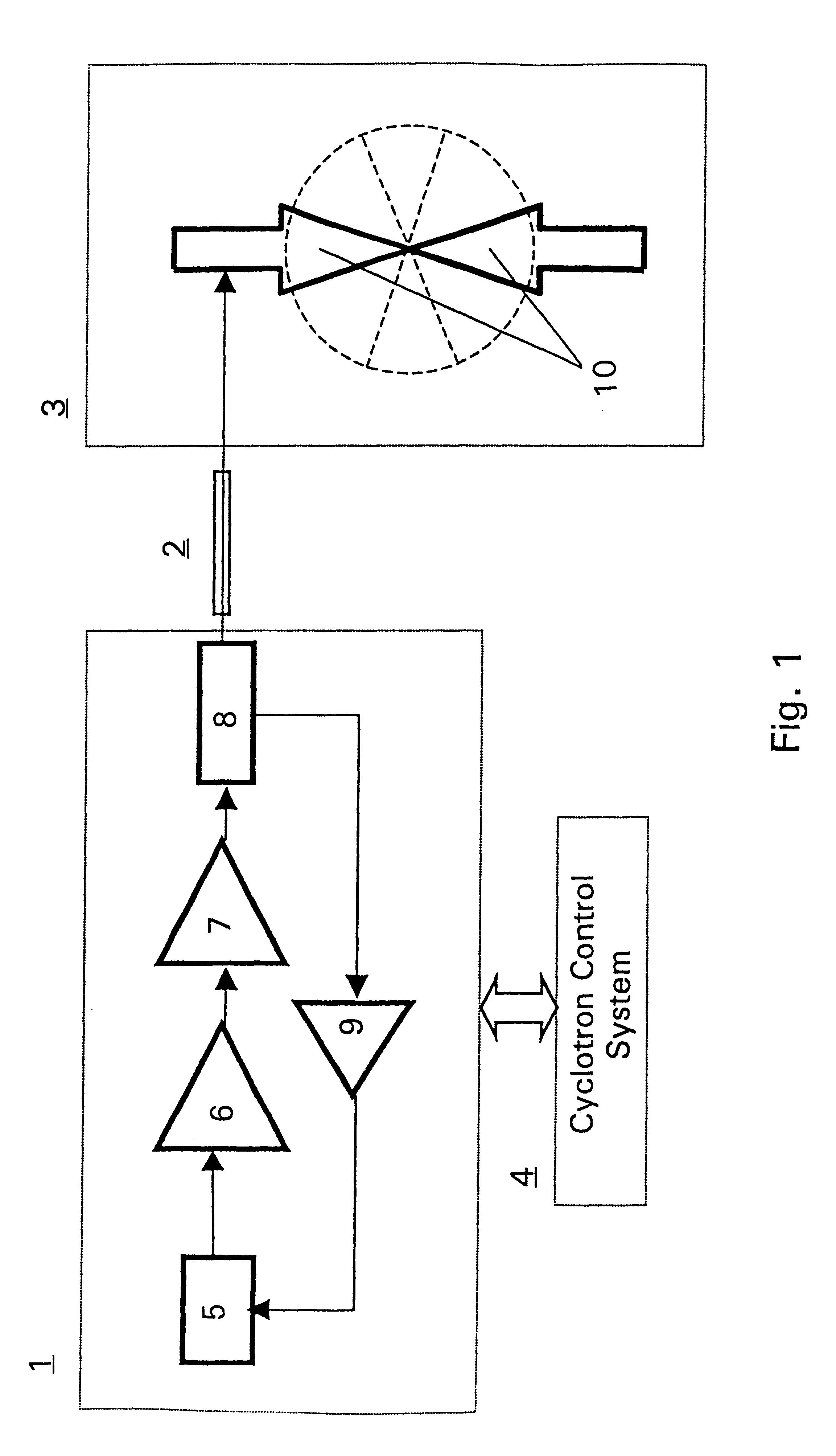
FIG. 1 discloses a block diagram illustrating a system applying the method according to the present invention. In the system according to FIG. 1 the stable frequency oscillator 1, which generates a predetermined frequency for the cyclotron device 3, tracks the actual resonance frequency of its RF electrode system 10 to maintain the operation of the RF electrode system at resonance for creating in the magnetic field of the cyclotron a beam of negative hydrogen ions for producing PET isotopes.

The high frequency power generator 1 is preferably of a synthesised type and frequency controlled by a feedback loop (i.e. the generated frequency will then have an offset being proportional to an analogue or a digital signal). The accelerating radio frequency signal is generated by a controlled frequency oscillator 5, the frequency of which is initially pre-set to a default frequency, in the illustrative embodiment of the order 100 MHz. The oscillator creates a signal at low power level which is...


PUM


Abstract

A method and a system for obtaining a proper resonance of the RF electrodes when using a preset or predetermined stable frequency oscillator in a cyclotron accelerator without using mechanical tuning devices. In order to maintain a high RF electrode voltage during operation the RF electrode system resonance is monitored and the frequency of the stable frequency generator is controlled by a feedback system continuously monitoring the matching of the oscillator output frequency and the resonance of the RF electrode system. Necessary small adjustments of the stable oscillator frequency to maintain a maximum matching to the resonance frequency of the RF electrode system are obtained by means of the feedback system to the stable oscillator. The feedback system relies on measured values obtained by a load phase sensor monitoring the output of the final RF power amplifier. A cyclotron control system in turn obtains the set and corrected oscillator frequency value and fine tunes further the magnetic field created in the accelerator device according to the frequency information obtained.

Description

This application is the national phase under 35 U.S.C. .sctn.371 of PCT International Application No. PCT / SE99 / 01662 which has an International filing date of Sep. 23, 1999, which designated the United States of America and was published in English.The present invention relates to a method and a system for Radio Frequency (RF) control and more exactly to a method and system for tuning the operation frequency and RF electrode system in a cyclotron without the use of any mechanical tuning devices.Production of radioisotopes normally takes place by means of a suitable particle accelerator, for instance a cyclotron, in which a beam of ions is accelerated. The radioisotopes are formed via nuclear reactions between an incident ion beam and a target medium, which can be a pressurised gas, a liquid or a solid.The acceleration of ions in a cyclotron is performed via a so-called RF electrode system maintained at high voltage (30-40 kV) oscillating with the same period time as the orbit revolu...

Claims


Application Information

Patent Timeline
Patent Type & Authority Patents(United States)
IPC IPC(8): H05H7/00H05H7/02H05H13/00H05H7/18
CPCH05H7/02H05H13/00Y02E30/10
Inventor BERGSTROM, JAN OLOF
Owner GEMS PET SYST
Learn More