Method for synchronizing an envelope inserter

Inactive Publication Date: 2002-07-09
DMT SOLUTIONS GLOBAL CORP
View PDF5 Cites 19 Cited by
  • Summary
  • Abstract
  • Description
  • Claims
  • Application Information

AI Technical Summary

Problems solved by technology

On occasion, however, a sheet in a sheet handling device will slip so that the motion of the axis does not necessarily indicate the motion of a sheet (or envelope).

Method used


Image

  • Method for synchronizing an envelope inserter
  • Method for synchronizing an envelope inserter
  • Method for synchronizing an envelope inserter

Examples


Embodiment Construction

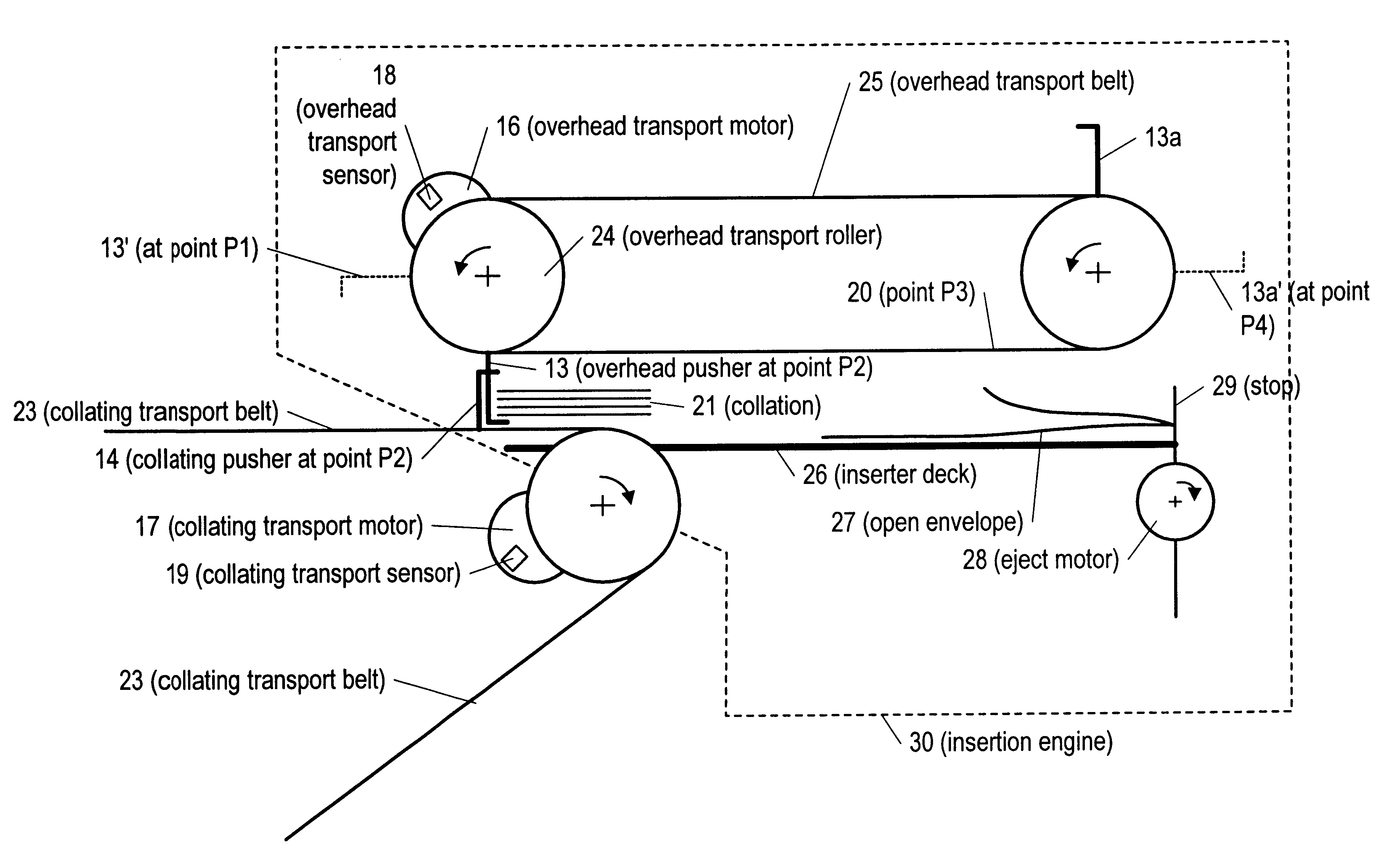
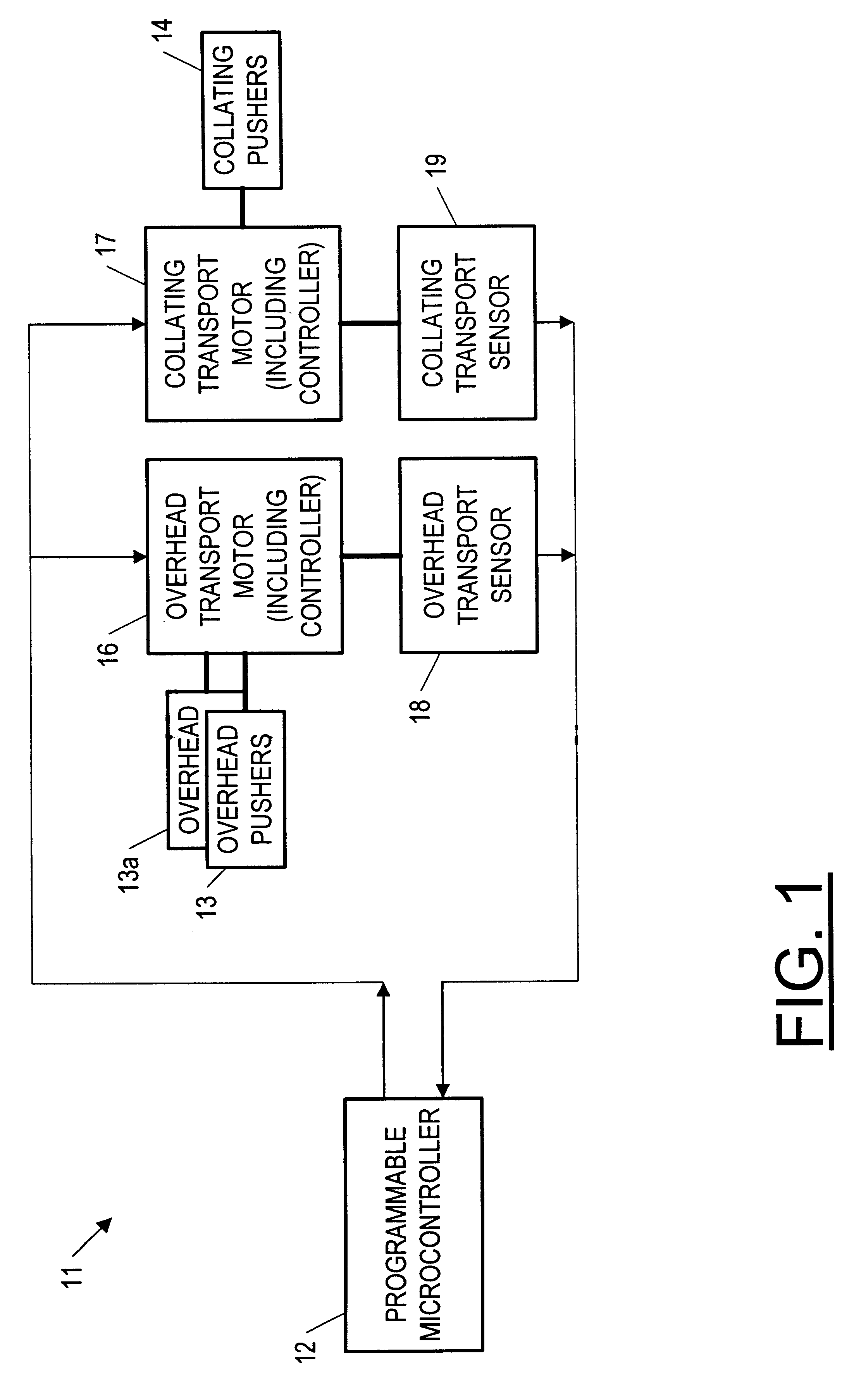
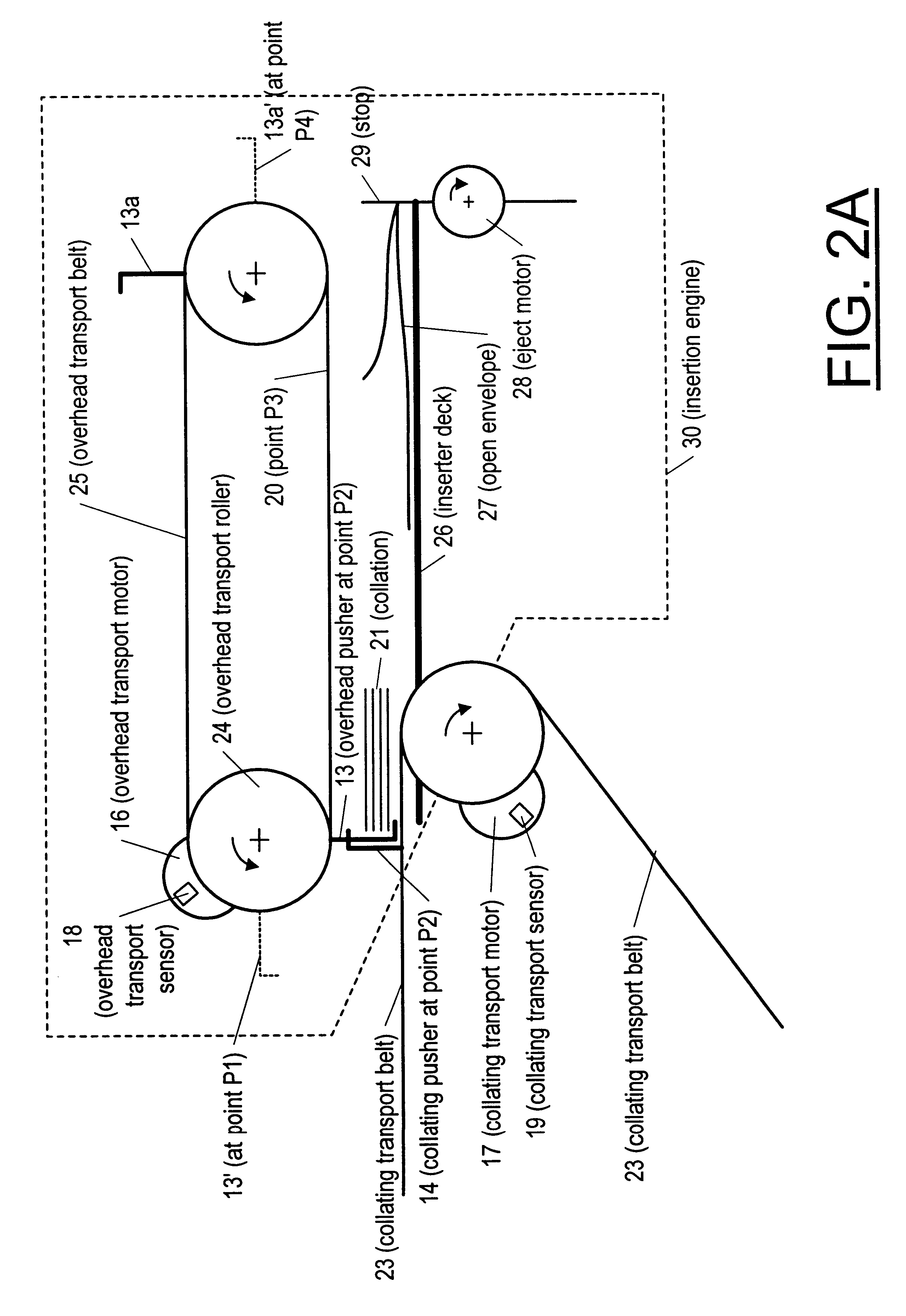
Referring now to FIGS. 1, 2A and 2B, a mail processing system 11 for gathering a collation and inserting it into an envelope is shown as including a programmable micro-controller (FIG. 1 only) that stores and executes instructions corresponding to a motion control profile according to the present invention. (Such a motion control profile is as described below in connection with FIGS. 2-4.) The microcontroller 12 communicates commands, associated with the stored instructions, to an overhead transport motor 16 (i.e. to its controller) and also to a collating transport motor 17, both included within an insertion engine 30. The microcontroller uses information provided by an overhead transport sensor 18 and a collating transport sensor 19 on which to base the commands it sends to the motors 16 and 17. The information provided by the sensors 16 and 17 allows so-called electronic gearing (displacement mapping) of the overhead transport motor 16 to the collating transport motor 17.

Referrin...


PUM


Abstract

A method for dynamically determining a motion control profile used in controlling motion of an axis of an overhead transport motor so as to be synchronized to the motion of a collating transport motor of an insertion engine used to insert a collation into an envelope when the collating transport motor causes a collating pusher to handoff the collation to an overhead pusher being driven by the overhead transport motor. The motion profile consists of a finite number of segments and repeats after the finite number of segments, the finite number of segments constituting a cycle. The method includes the steps of: electronically gearing the overhead transport motor to the collating transport motor from the beginning of a cycle until handoff; based on position information provided by a sensor, determining whether the collating transport is decelerating between handoff and insertion; and using either forward integration or electronic gearing of the overhead transport motor to the collating transport motor up until the collating transport motor is first determined to be decelerating between handoff and insertion, and using forward integration when the collating transport motor is first determined to be decelerating between handoff and insertion and continuing the forward integration until insertion. In some applications, the forward integration is used when the collating transport motor is first determined to be decelerating between handoff and insertion and continuing the forward integration until the end of the cycle.

Description

The present invention pertains to methods for automatically assembling or collating or singulating of sheets of media such as paper, such as is done by mailing systems when assembling and inserting sheets into envelopes. More particularly, the present invention pertains to controlling the motion of pushers that push sheets through a sheet handling device, such as a mailing machine, a postage meter, an envelope printer or inserter, and including a high-speed inserter.BACKGROUND OF INVENTIONGeneral DiscussionA typical sheet or envelope handling device includes various structures, motors and sensors. For example, a typical envelope handling device includes an envelope feeding structure for feeding an envelope or a batch of envelopes in singular fashion in a downstream path of travel to a work station. Typical envelope handling devices employ ejection rollers or ejection belts operating at a constant speed, or at some speed that varies as a function of time, speeds chosen so as to avoid...

Claims


Application Information

Patent Timeline
Patent Type & Authority Patents(United States)
IPC IPC(8): G06F7/00G07B17/00
CPCG07B17/00467G07B2017/00491
Inventor CHODACK, JEFFREY L.FRANCISCO, ROBERTSALAZAR, EDILBERTO I.SUSSMEIER, JOHN W.
Owner DMT SOLUTIONS GLOBAL CORP
Why Eureka
Try Eureka