Storage equipment and storage method

Inactive Publication Date: 2002-07-16
TSUCHIYA DAIRY EQUIP MFG +2
View PDF7 Cites 9 Cited by
  • Summary
  • Abstract
  • Description
  • Claims
  • Application Information

AI Technical Summary

Benefits of technology

Moreover, since the storage space can be maintained at a high humidity by means of saturated water vapor pressure, storage of objects under low-temperature, high-humidity environment can be realized.
Therefore, it becomes possible to provide an environment suitable for storage of agricultural products (potatoes, vegetables, fruits, live flowers, etc). Furthermore, since the storage space can be maintained at the temperature of 0.degree. C. approximately, the system may be used also for freezing storage of frozen articles frozen below zero.
Further, due to the relationship between the temperature and density of the air (i.e. the lower the temperature, the higher the humidity), even if the entrance-exit opening is kept open during the entry or exit of the objects into or from the storage space, in case the outside air temperature is higher than the inside air temperature of the storage space, it is possible to minimize entry of the outside air into the inner space of the heat-insulating outer shell. Hence, the maintenance of the temperature of the storage space may be effected easily.
Moreover, as the ice storage water tank disposing space is interposed between the storage space and the outside, the ice storage water tank disposing space not only provides cold to the storage space, but also guards the storage space, whereby the influence from the environmental change of the outside air to the storage space may be advantageously reduced. Accordingly, it becomes possible to continue to provide storage for the storage objects under even better conditions for a longer period of time.
And, by minimizing heat loss associated with entry and exit of the storage objects, storage of the storage objects is made possible with maintaining the refrigerating environment stable for a longer period of time.

Problems solved by technology

Also, in the conventional storage facility too, there is the problem of large consumption of electricity since refrigerating cycle is employed as the heat source.
Moreover, in he case of such method using refrigerating cycle, in order to maintain the low temperature inside the storage house of the vegetables, not only the respiration heat is absorbed from the vegetables, but also significant dehydration of the vegetables occurs as the result.
Hence, a humidifier or the like needs to be employed, but, this too adds to the electricity consumption.
As a result, significant costs will be needed for transportation of snow and building of the facility.
Also, in cold districts without snow accumulation, the snow must be transported from a distant place, hence leading to especially high costs.

Method used


Image

  • Storage equipment and storage method
  • Storage equipment and storage method
  • Storage equipment and storage method

Examples


first embodiment

[First Embodiment]

An embodiment of a low-temperature, high-humidity storage house according to the present invention will be described with reference to FIG. 4. This is an embodiment in which the storage house is installed under the ground of a house. A storage space 3 is provided inside a building structure having heat-insulated construction. After ice is made by an ice maker described later with reference to FIG. 3, an outside-air inlet opening 1a and an inside-air outlet opening 1b are closed respectively by an air-inlet damper 31 and an air-outlet damper 32. The degree of heat insulation provided by a heat-insulating wall 42 should be such that the insulating material has a thickness sufficient to prevent the ice from being melted until a desired time during a warm season, due to reception of heat. In the case of this embodiment, it is preferred that after the making of ice, the temperature of the storage space 3 be monitored and storage into the storage space be waited until th...

second embodiment

[Second Embodiment]

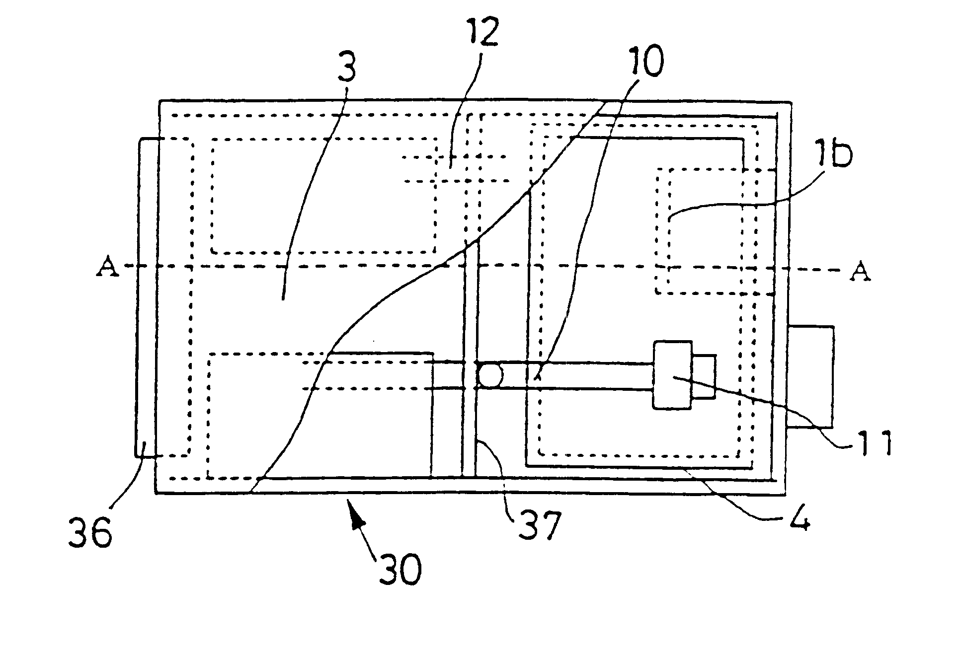
FIG. 6 shows an embodiment capable of storage also during winter when the outside temperature is sub-zero. In this FIG. 6, a building construction 30 having heat insulating structure includes a heat insulating wall 41 and another heat insulating wall 37 interposed between the storage space 3 and the ice storage water tank disposing space 5 so as to prevent direct introduction of sub-zero outside air through the outside air inlet opening 1a into the storage space 3. At an upper region inside the ice storage water tank disposing space 5, there is provided a fan 11 for feeding moist air abundantly present in the upper region in the ice storage water tank disposing space 5 via a first flow passage 10 into a cool air inlet opening 38. In the course of this, inside the storage space 3, there occurs respiration by the fresh air introduced from the lower region and the warmed air flows through a return opening 12 formed at an upper portion to be returned into the ice stor...

third embodiment

[Third Embodiment]

FIG. 8 is an embodiment wherein a storage facility T3 is installed in a house.

Incidentally, the constructions of those parts not particularly described are identical to those in the first and second embodiments described above.

Inside a heat insulating outer shell 1, there are provided a first ice storage water tank disposing space 5A capable of communicating with the outside, a storage space 3, and a second ice storage water tank disposing space 5B interposed between the first ice storage water tank disposing space 5A and the storage space 3. The heat insulating outer shell 1 is formed such that the first ice storage water tank disposing space 4A is disposed outdoors and the storage space 3 and the second ice storage water tank disposing space 5B are disposed indoors.

In the instant embodiment, the heat insulating outer shell 1 has a cubic shape.

In the storage space 3, steel containers 4 capable of resisting freezing and thawing of ice are installed in different lev...


PUM


Abstract

A storage system comprises: a heat-insulating outer shell (1) capable of insulating inner space (V); an ice storage water tank (4) capable of storing water therein disposed in an ice storage water tank disposing space (5) provided in the inner space (V) of the heat-insulating outer shell (1); a storage space (3) for storing objects (2) to be stored provided in the inner space (V) of the heat-insulating outer shell (1); an outside-air inlet opening (1a) provided at a lower portion of the heat-insulating outer shell (1), the inlet opening being capable of introducing outside air into the inner space (V); an inside-air outlet opening (1b) provided at an upper portion of the heat-insulating outer shell (1), the outlet opening being capable of discharging inside air from the inner space (V) of the heat-insulating outer shell (1) to the outside; and an object entrance-exit opening (7) provided at an upper portion of the heat-insulating outer shell (1) for allowing entrance-exit of the objects (2) to and from the storage space (3).

Description

1. Field of the InventionThe present invention relates to a storage facility and a storage method using the storage facility. For example, the invention relates to a storage facility and a storage facility involving low-temperature, high-humidity storage of an object to be stored (e.g. agricultural product such as potato, vegetable, fruits, etc.), or precooling of vegetable, and also to a storage method using the system.2. Description of the Prior ArtAs the conventional storage facility and storage method of the above-noted type, there are known the system and method utilizing the direct-cooling refrigerating cycle. For example, there is known a system and method utilizing such direct-cooling refrigerating cycle from e.g. Japanese laid-open patent gazette No. Hei. 5-26557.Basically, this system is designed to maintain low temperature by absorbing respiration heat of the vegetable stored inside a storage house. Accordingly, for reducing the temperature its inside, this system employs...

Claims


Application Information

Patent Timeline
IPC IPC(8): F25D3/04F25D3/00
CPCF25D3/04
Inventor DOKOSHI, JUN
Owner TSUCHIYA DAIRY EQUIP MFG
Why Eureka
Try Eureka