Forceps, in particular biopsy forceps

a forceps and biopsy technology, applied in the field of forceps devices, can solve the problems of difficult fitting, wear and failure, and other components, too, and achieve the effect of easy adjustment and adjustment, and easy adjustmen

Inactive Publication Date: 2002-07-30
EUROBIOPSY
View PDF6 Cites 30 Cited by
  • Summary
  • Abstract
  • Description
  • Claims
  • Application Information

AI Technical Summary

Benefits of technology

Thus, by virtue of the invention, the internal surface of the jaw-piece arm may have a straight profile, or on the contrary, a profile which may vary, going progressively toward the axis of the sheath as it penetrates further into the sheath, thereby enabling the kinematics of the movement of the jaw-pieces away from each other to correspond to the shape of the ramp thus formed. The external face of the arms is also shaped when being moved closer to the axis, preferably so as to constantly slide on the end of the internal surface of the sheath and thus to avoid any free movement of the arm between the rod and the internal surface of the sheath.
It will be understood that a forceps device has thus been produced which is mechanically very simple and which is composed of a very small number of components, namely the two jaw-pieces, the transverse rod, the head which terminates the sheath, and optionally a tubular section added onto the end of the sheath and forming the internal surface for guiding and receiving, on its end, the rod.
This results in easy assembly and dismantling, simple maintenance and almost complete freedom from the risks of breaking or of failure.

Problems solved by technology

They are therefore expensive, difficult to fit and subject to wear and failures.
At the linkage to the cable, they lead to torsional effects inducing fatigue in the cable which may cause it to break.
Other components, too, may be exposed to excessive stresses, so that in the final analysis these forceps have a large number of drawbacks.
Moreover, the presence of the links, an articulation end of which extends along the axis of the forceps, makes it hard to add an auxiliary tool such as a barb extending along the axis of the forceps.
Furthermore, it is extremely difficult to co-ordinate the movement of displacing the barb with the movement of opening the jaw-pieces of the forceps.

Method used


Image

  • Forceps, in particular biopsy forceps
  • Forceps, in particular biopsy forceps
  • Forceps, in particular biopsy forceps

Examples


Embodiment Construction

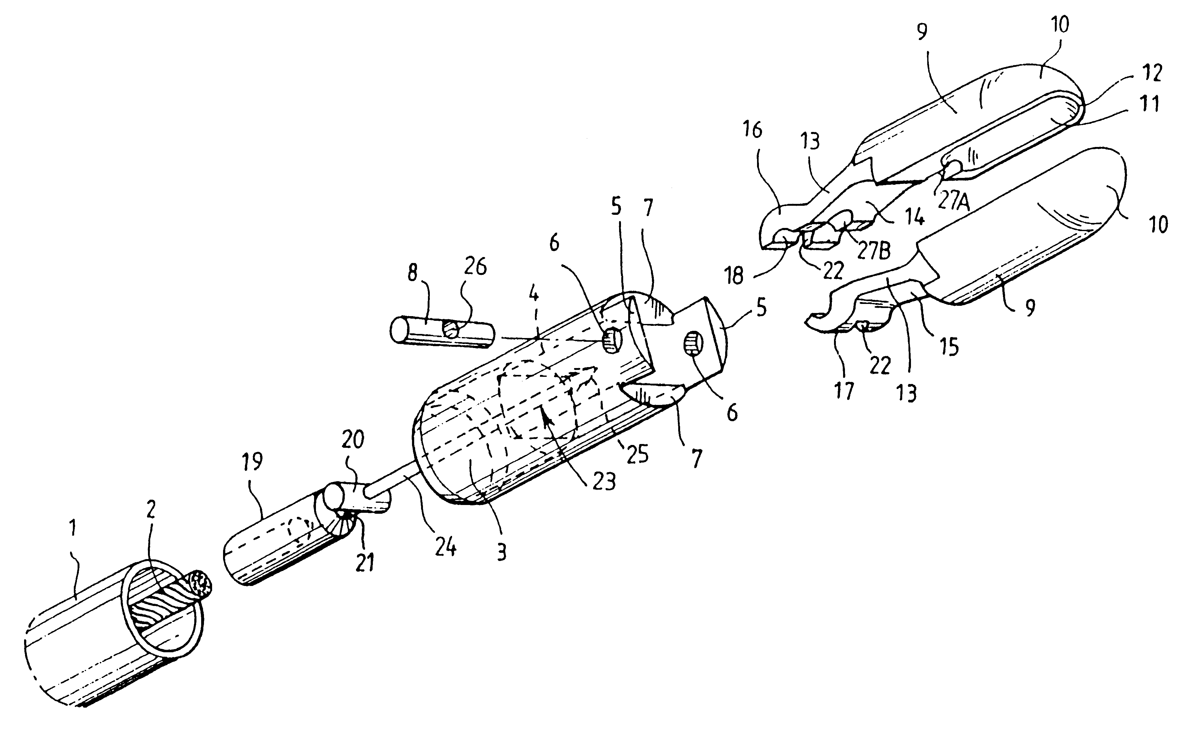
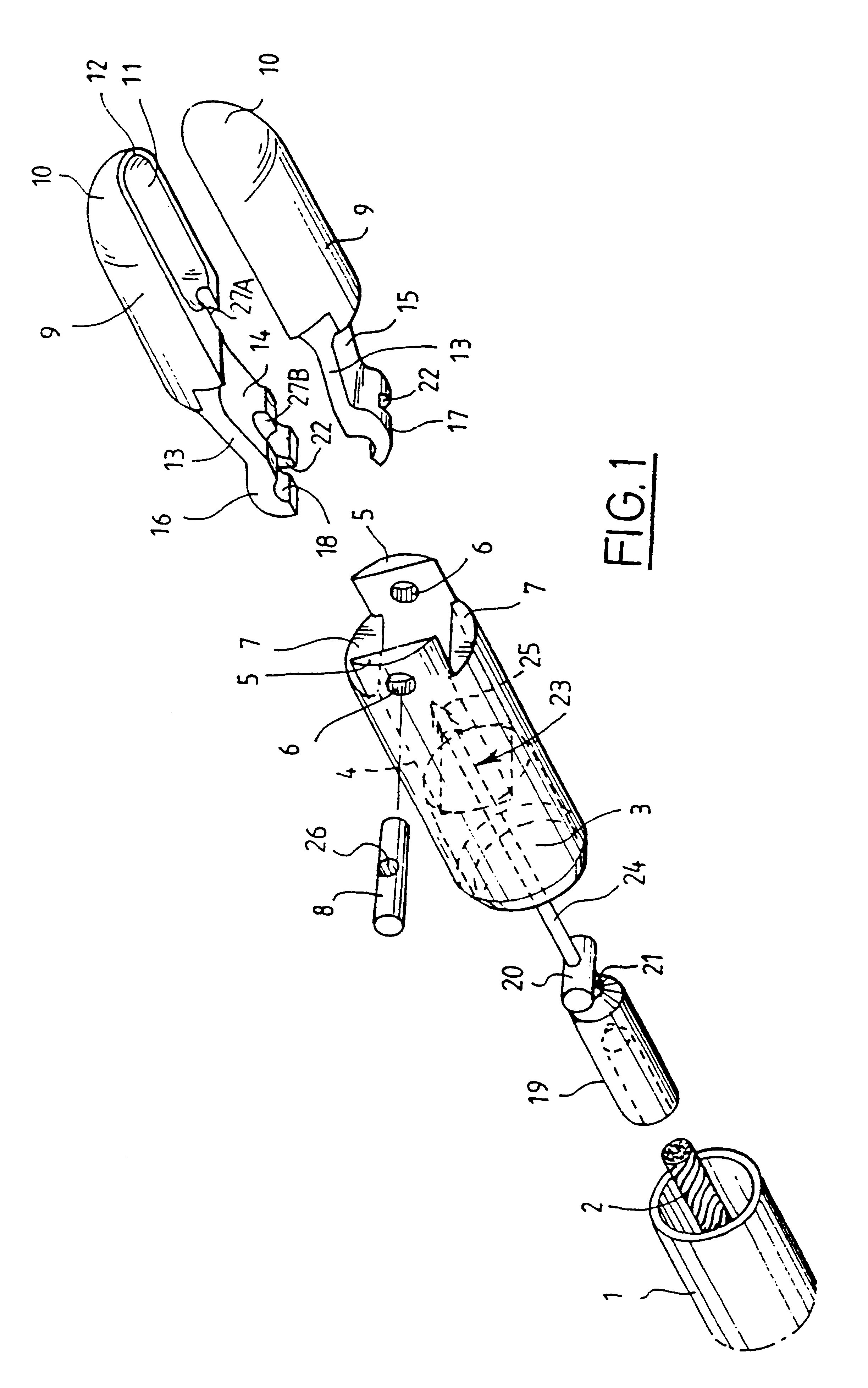
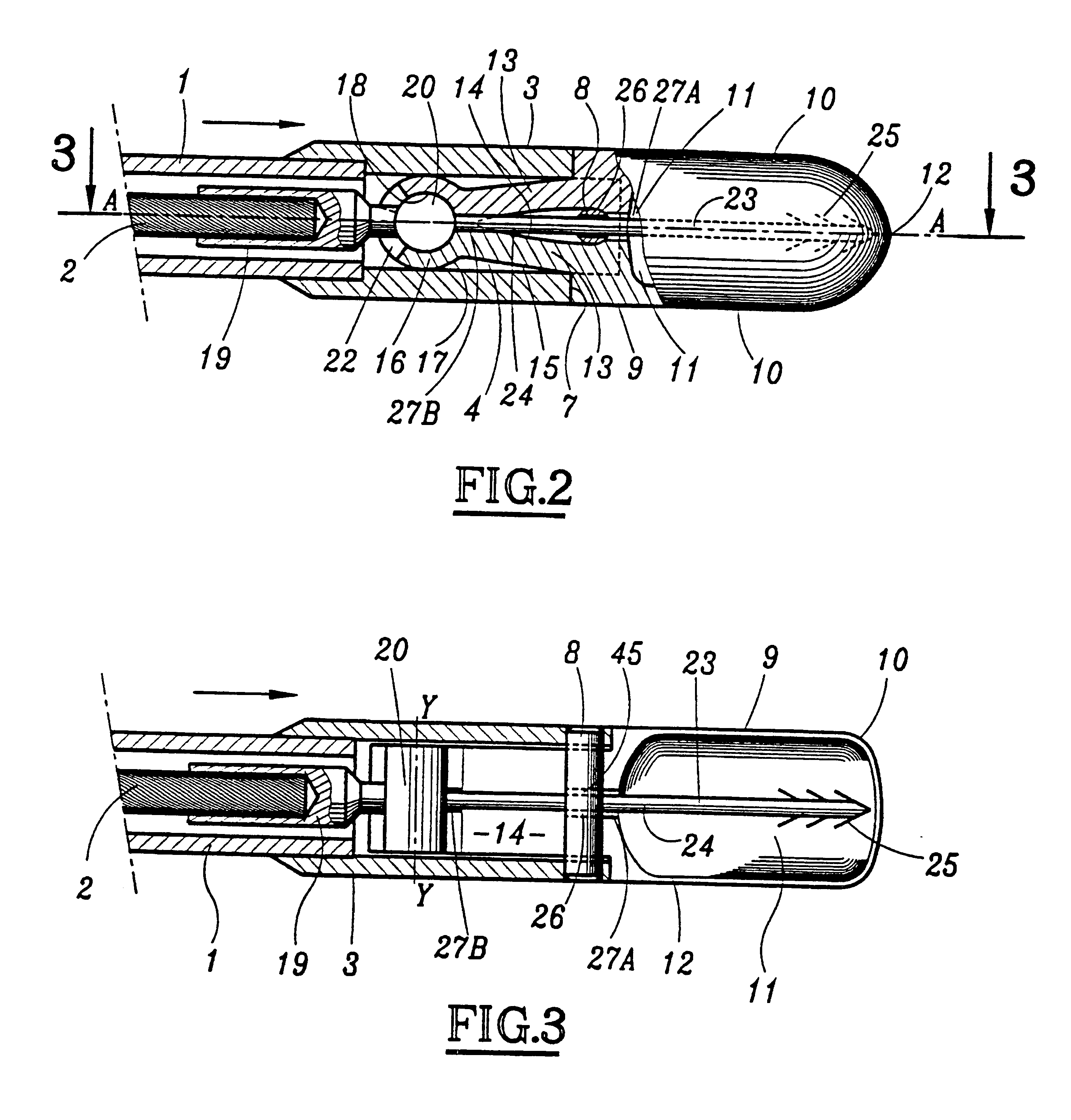
The biopsy forceps shown in the figures has an elongate sheath 1 inside which a semi-rigid cable 2 may move longitudinally, one of the ends, not shown, of which cable is connected to a maneuvering grip of the usual type in this kind of forceps. Advantageously, means are provided for holding one or other of the sheath and the cable in position with respect to the organ to be treated, and for moving whichever of the sheath and the cable is not being held.

The sheath 1 has, on its end, a metal tubular element 3, the outer surface of which is cylindrical, and which includes a central passage 4 of rectangular or square cross section. At its end remote from the sheath, the cylindrical component 3 is cut into the form of crenels so as to form two extensions 5 through which pass aligned holes 6, the common geometrical axis of which is located slightly above the plane of the two lowermost edges 7 of the crenels. Thus, the bottom part of the holes 6 lies substantially in the plane of these low...


PUM


Abstract

Forceps instrument comprising a sheath having a first end and an elongated maneuvering element slidably disposed in the first end of said sheath. The sheath has an axis. The instrument comprises two jaw-pieces, at least one of the jaw-pieces being movable away from and toward the other of the jaw-pieces when the maneuvering element slides axially in the first end of the sheath. The jaw-pieces have, in an extension of a part thereof, an arm extending progressively toward the axis of the sheath so as to form a first, internal, inclined surface extending progressively toward the axis and facing the latter and a second, external, inclined surface extending progressively toward the axis and facing the internal surface of the sheath. The arm has a convex excrescence which is slidable substantially against the internal surface of the sheath, the excrescence having a concave hollow cavity facing the axis. The sheath has, near its end beyond which the jaws extend, a transverse element against which the internal surface of the arm slides. The elongate maneuvering element terminates in a head housed in the concave hollow cavity so that, when the elongate maneuvering element is moved toward a free end of the sheath, it pushes the jaw-pieces back beyond the end of the sheath, thus causing the internal surface of the arm, which slides over the transverse element, to pivot by a ramp effect, moving the at least one jaw of the jaw-pieces away from the other jaw, the movement away being permitted by the inclination of the external surface which protrudes from the end of the internal surface of the sheath. The excrescence of the arm pivoting, during this movement, about the head while still being guided in the sheath, reverse movement of the maneuvering element causing the jaw-pieces to move closer by a reverse movement. The transverse element includes a passage having an axis substantially parallel to the axis of the sheath for accommodating an auxiliary tool between the two jaw-pieces.

Description

The present application is the U.S. National Phase of PCT / FR98 / 01777.1. Field of the InventionThe present invention relates to a forceps device, such as, a biopsy forceps, that is to say, a forceps having two jaw-pieces capable of being moved away from each other, of being moved closer to each other and, while they are moving closer to each other, of cutting or detaching a specimen of body tissue which is seized between the two jaw-pieces of the forceps and which can subsequently be recovered outside the body.The invention also extends to other instruments which can be used in medicine or in surgery, such as, for example, forceps instruments having no cutting effect, for providing a clamping effect, or retractors, or else scissors for surgical use, or any other instrument of this kind having two elements, at least one of which is capable of being moved away from and of being moved toward the other.2. Discussion of the Background InformationThe currently known biopsy forceps have two...

Claims


Application Information

Patent Timeline
Patent Type & Authority Patents(United States)
IPC IPC(8): A61B10/00A61B10/06
CPCA61B10/06
Inventor HUGUENY, JEAN-MARIESABIN, JEAN-LOUISSABIN, PIERRE JEAN-CLAUDEWARNIER, ANTOINE
Owner EUROBIOPSY
Why Eureka
Try Eureka