Active gauge cutting structure for earth boring drill bits

a cutting structure and active gauge technology, applied in the field of drill bits, can solve the problems of reducing directional control, affecting cutting accuracy, and increasing constrain

a cutting structure and active gauge technology, applied in the field of drill bits, can solve the problems of reducing directional control, affecting cutting accuracy, and increasing constrain

US6427792B1Inactive Publication Date: 2002-08-06CAMCO INT

Image

  • Active gauge cutting structure for earth boring drill bits
  • Active gauge cutting structure for earth boring drill bits
  • Active gauge cutting structure for earth boring drill bits

Examples


Embodiment Construction

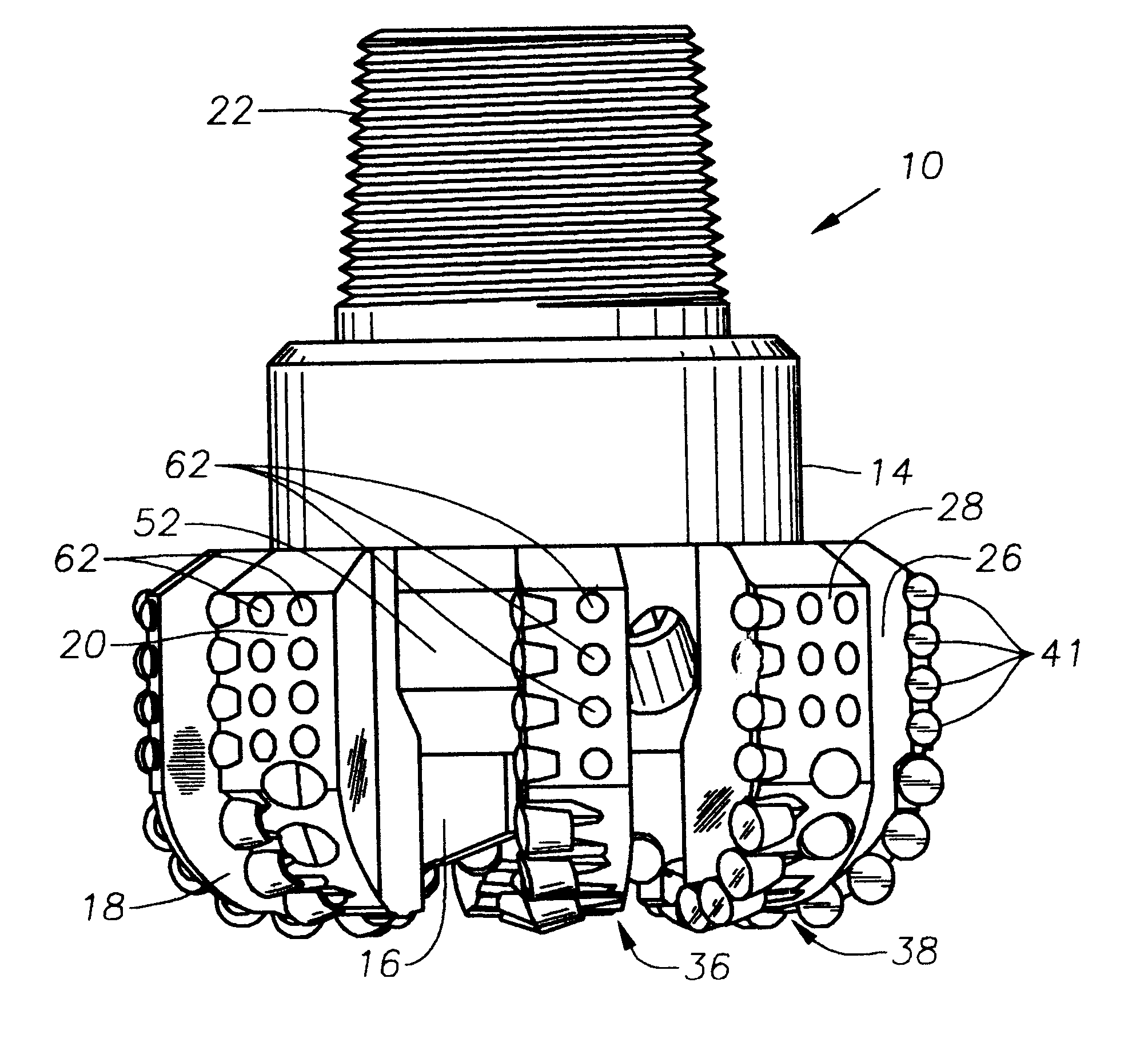
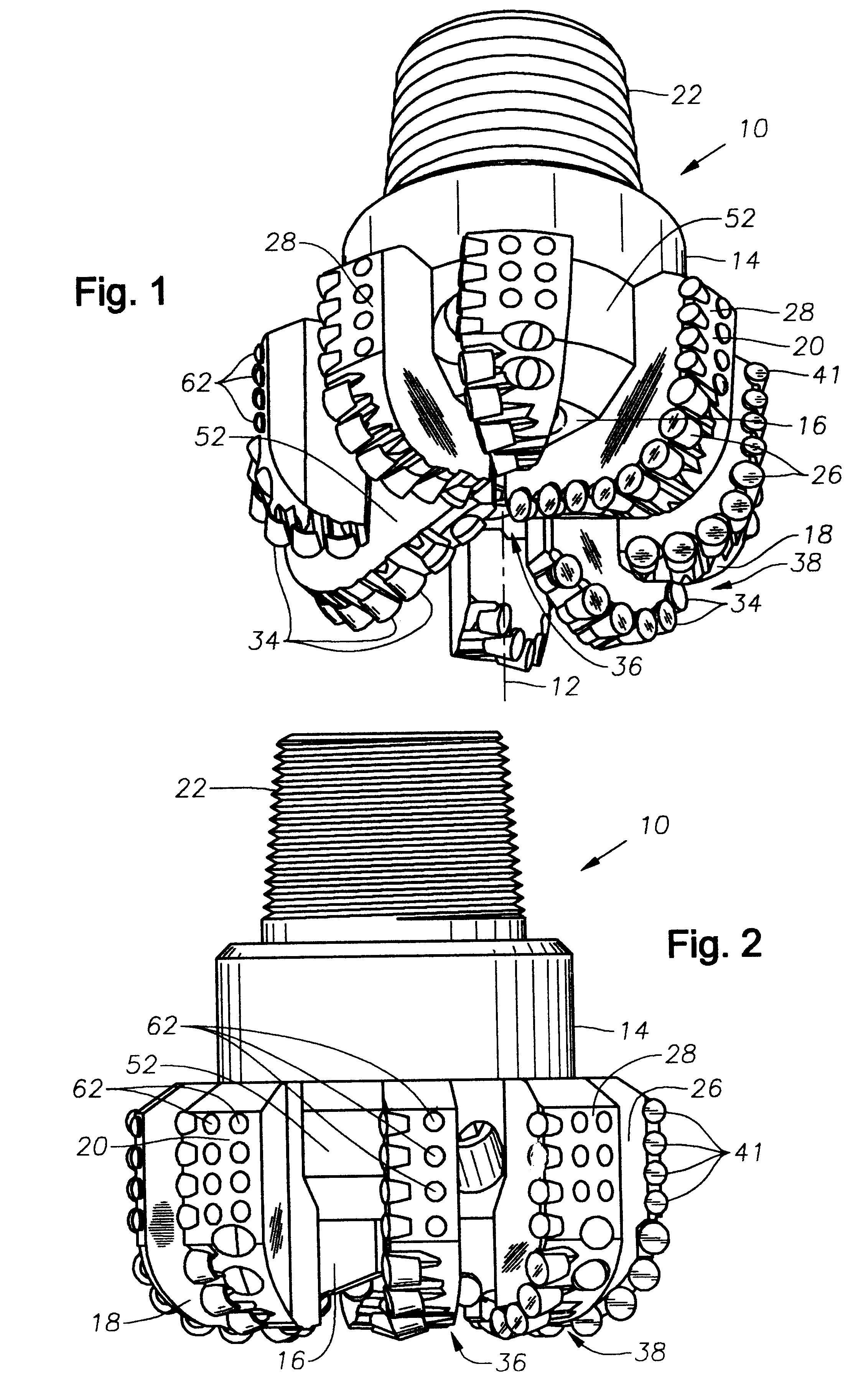
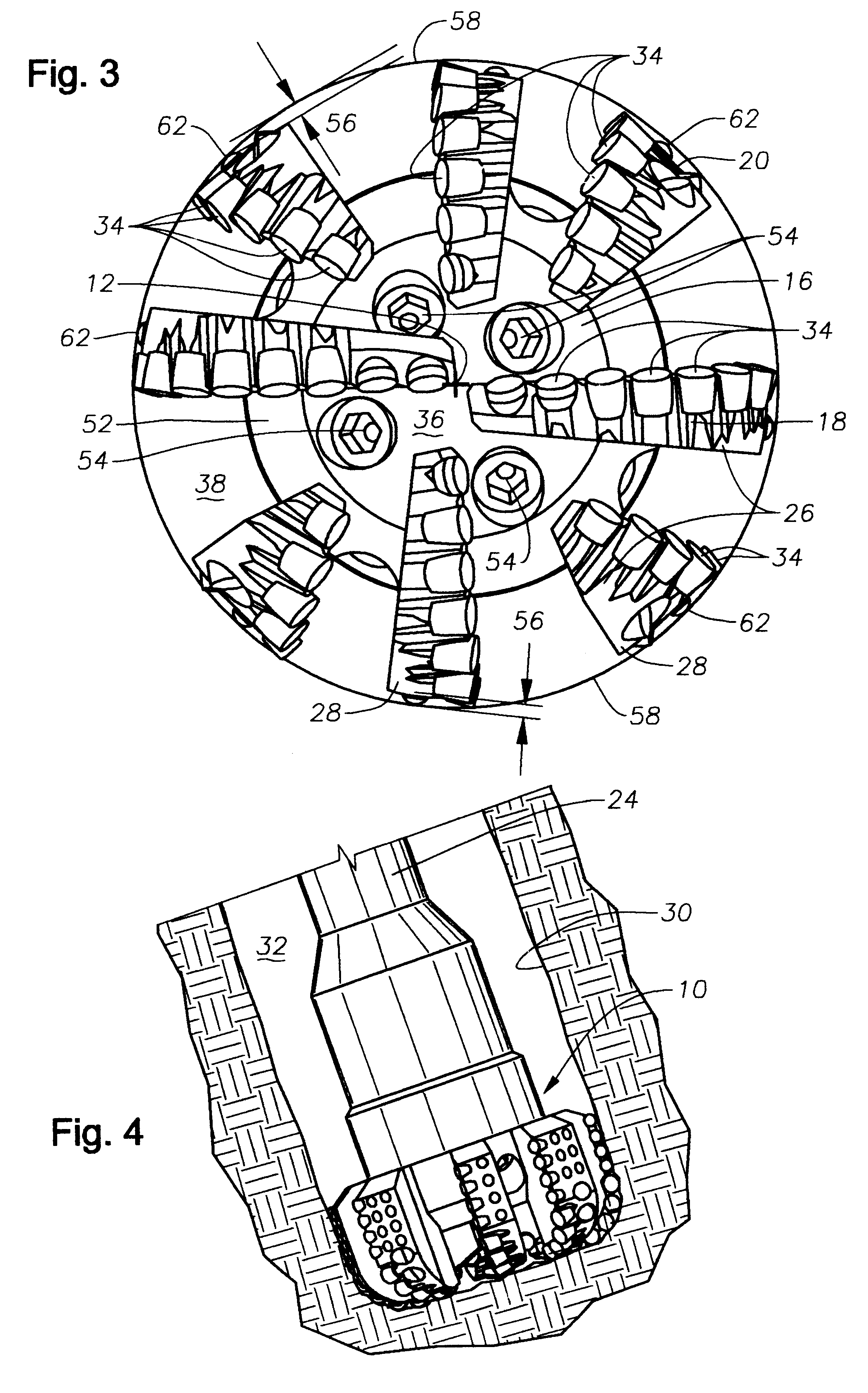
Turning now to the drawing FIGS. 1 through 4, a fixed cutter drill bit of the present invention is illustrated and generally designated by the reference numeral 10. The drill bit 10 has a central axis of rotation 12 and a bit body 14 having a leading face 16, an end face 18, a gauge region 20, and a shank 22 for connection to a drill string 24. A plurality of blades 26 are upstanding from the leading face 16 of the bit body and extend outwardly away from the central axis of rotation 12 of the bit 10. Each blade 26 terminates in a gauge pad 28 which faces a wall 30 of the borehole 32.

A number of cutters 34 are mounted on the blades 26 at the end face 18 of the bit 10 in both the cone region 36 and the shoulder region 38 of the end face 18. Another group of cutters 34 are mounted on the gauge pads 28.

As shown in FIG. 6, each of the cutters 34 partially protrude from their respective blade 26 and are spaced apart along the blade 26, typically in a given manner to produce a particular t...


PUM


Abstract

The present invention is a drag-type drill bit for drilling a borehole in the earth. The bit is designed to rotate about a central axis of rotation and has a bit body having a leading face, an end face, a gauge region, and a shank for connection to a drill string, a plurality of nozzles in the bit body for delivering drilling fluid to the end face, a plurality of blades upstanding from the leading face of the bit body and extending outwardly away from the central axis of rotation of the bit. Each blade terminates in a gauge pad with a surface which faces a wall of the borehole. A first plurality of cutters are mounted on the blades at the end face of the bit body and a second plurality of cutters are mounted the gauge pads and arranged such that in operation, they cut the wall of the borehole. Each one of the second plurality of cutters has a backrake less than or equal to about 20 degrees. A plurality of non-cutting bearing element are mounted on the gauge pads in a trailing relationship relative to the rotation of the bit behind at least some of the second plurality of cutters. The surface of each gauge pad is relieved from the borehole by at least 3 mm.

Description

1. Field of the InventionThe invention relates to drill bits used for boring or penetrating the earth. In particular, the invention is a new fixed cutter drill bit with cutting elements arranged in a manner to actively cut the gauge portions of a borehole in the earth to facilitate directional drilling.2. Description of the Related ArtUntil relatively recently, a primary design goal for the designers of both fixed and rolling cutter earth boring drill bits was to design bits which would drill straight holes through the earth in spite of the tendency of the bit to follow along the dips and strikes of bedded rock formations in the earth. A great body of design knowledge accumulated over the years has taught these bit designers how to adjust the bit design parameters to accomplish straight hole drilling.However, a division occurred early on in the body of straight hole drilling knowledge between fixed cutter drill bits and rolling cutter drill bits. Even though the broad concepts to ac...

Claims


Application Information

Patent Timeline
06 Aug 2002
Publication
US6427792B1
IPC
E21B7/06; E21B17/00; E21B17/10; E21B7/04; E21B10/00; E21B10/42; E21B10/46; E21B10/54; E21B10/43; E21B10/55
CPC
E21B7/064; E21B10/43; E21B10/55; E21B17/1092; E21B10/602
Inventors
ROBERTS, TOM; BARTON, STEVEN