
Device for varying the energy of a particle beam extracted from an accelerator

a particle beam and accelerator technology, applied in the direction of electric discharge lamps, instruments, electromechanical components, etc., can solve the problems of energy degraders, relatively complex accelerator types, and inability to produce them reliably,

Inactive Publication Date: 2002-08-13
ION BEAM APPL
View PDF1 Cites 187 Cited by
  • Summary
  • Abstract
  • Description
  • Claims
  • Application Information

AI Technical Summary

Benefits of technology

The present invention aims to provide a device which would make it possible to vary the energy of the beam extracted from a particle accelerator, in particular from a fixed-energy particle accelerator.
More particularly, the present invention aims to provide a device which would make it possible to vary almost continuously the energy of a beam extracted from a particle accelerator.
This advantageously allows to keep the characteristics in energy dispersion and the optical qualities of the beam.

Problems solved by technology

Nevertheless, this type of accelerator is relatively complex to produce, and is accordingly more expensive and less reliable than particle accelerators which produce beams of fixed energy such as cyclotrons.
Nevertheless, the main drawback of such devices, which are also known as energy degraders, lies in the fact that the block of material deteriorates the energy resolution of the degraded beam.
These drawbacks (increase in divergence and in energy dispersion) may lead to a situation in which the emittance of the beam is too high to meet the entry emittance constraints set by the optical elements of the beam which are located downstream along the beam transport line.
Nevertheless, by using such elements, it is observed that the intensity of the beam is further reduced, also causing a large activation of the various elements.
Nevertheless, this application does not propose to perform a continuous variation of the energy of the beam extracted from a particle accelerator, and in particular a fixed-energy particle accelerator.

Method used


Image

  • Device for varying the energy of a particle beam extracted from an accelerator
  • Device for varying the energy of a particle beam extracted from an accelerator
  • Device for varying the energy of a particle beam extracted from an accelerator

Examples


Embodiment Construction

The present invention will be described in greater detail with reference to the figures which represent one particularly preferred embodiment of the present invention.

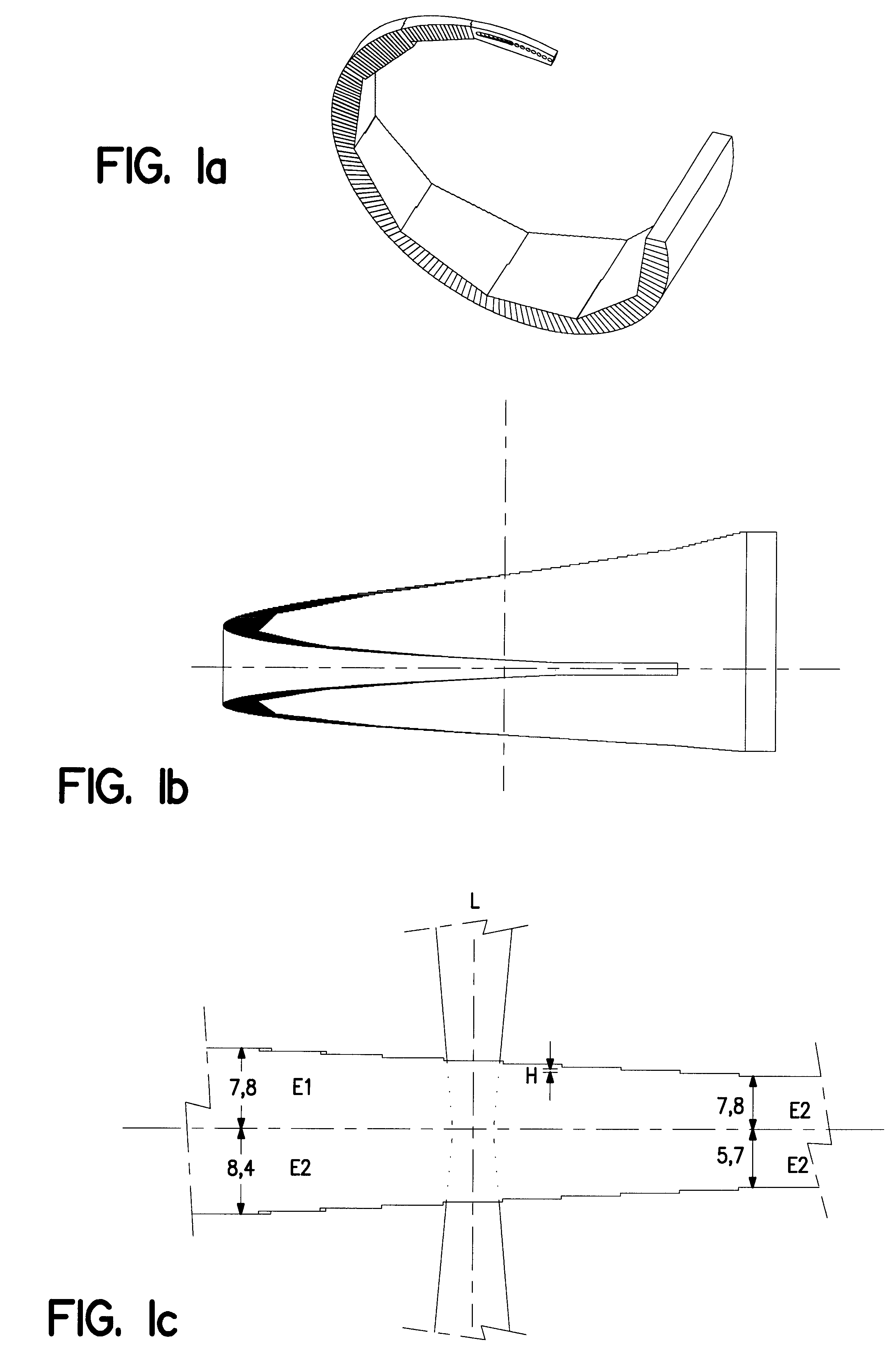
FIGS. 1a and 1b represent a degrader used in the device according to the present invention, substantially consisting of a block of material, the thickness of which is discretely variable by steps. This energy degrader will make it possible to roughly determine the desired energy value. Usually, an analysis magnet will be added to this energy degrader downstream said degrader, so as to allow finer adjustment of the desired energy value.

As represented in FIG. 1c, the energy degrader according to the invention is of "staircase" shape, for which each level or "step" has a different thickness corresponding to a given energy variation, the thickness E1+E2 being defined as the distance between the entry face and the exit face of the particle beam. Moreover, the width L of the successive steps is variable, and increases as a f...


PUM


Abstract

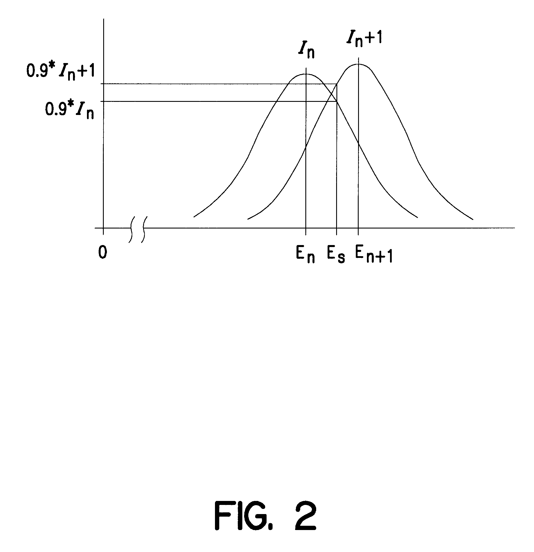
A device for varying the energy of a particle beam extracted from a fixed-energy particle accelerator includes a block of energy degrading material positioned in the path of the particle beam. The block of energy degrading material is preferably in the form of a ring arranged on a wheel. The ring is of a staircase configuration, having discrete steps defining a thickness between parallel entry and exit faces. According to one aspect of the invention, the block is configured so that the particle beam energy variation reaches a maximum at the edges of each step. This upper limit is also the lower limit of the next step. Thus, continuous energy variation is possible despite the fact that the thickness of the block varies in discrete steps.

Description

1. Field of the InventionThe present invention relates to a device for varying the energy of a particle beam extracted from a particle accelerator.The present invention also relates to the use of said device.2. State of the ArtCertain applications involving the use of beams of charged particles also require the energy of these particles to be rapidly varied.To do this, one solution consists in using an accelerator capable of producing, intrinsically, an extracted particle beam whose energy is variable. In this regard, it may be proposed to use an accelerator such as a synchrotron capable of producing within this accelerator itself a particle beam, the energy of which is variable. Nevertheless, this type of accelerator is relatively complex to produce, and is accordingly more expensive and less reliable than particle accelerators which produce beams of fixed energy such as cyclotrons.As a result, it has been proposed to equip such fixed-energy accelerators with a device whose functio...

Claims


Application Information

Patent Timeline
IPC IPC(8): G21K1/00G21K1/10H05H7/00H05H13/00H05H7/12
CPCG21K1/10H05H7/00H05H13/00
Inventor JONGEN, YVESPOREYE, VINCENT
Owner ION BEAM APPL
Learn More