Adaptive acoustic channel equalizer & tuning method

a technology of acoustic channel equalizer and tuning method, which is applied in the direction of instruments, surveyors, borehole/well accessories, etc., can solve the problems of significant attenuation and interference, significant signal distortion, and reduce the conditions under which acoustic data transmission may be effectively utilized

Inactive Publication Date: 2002-08-13
WELLDYNAMICS INC
View PDF19 Cites 73 Cited by
  • Summary
  • Abstract
  • Description
  • Claims
  • Application Information

AI Technical Summary

Benefits of technology

Numeral references are employed to designate like parts throughout the various figures of the drawing. Terms such as "left," "right," "clockwise," "counter-clockwise," "horizontal," "vertical," "up" and "down" when used in reference to the drawings, generally refer to orientation of the parts in the illustrated embodi

Problems solved by technology

There are many practical problems associated with using this scheme.
When tubing, drill pipe or casing are used as an acoustic transmission channel, there is often significant signal distortion due to reflective interfaces in the channel such as tool joints, collars or other upsets.
Additionally, there can be significant attenuation and interference associated with the fluid system within the wellbore and echos of the acoustic signals themselves within the wellbore.
These factors significantly reduce the conditions under which acoustic data transmission

Method used


Image

  • Adaptive acoustic channel equalizer & tuning method
  • Adaptive acoustic channel equalizer & tuning method
  • Adaptive acoustic channel equalizer & tuning method

Examples


Embodiment Construction

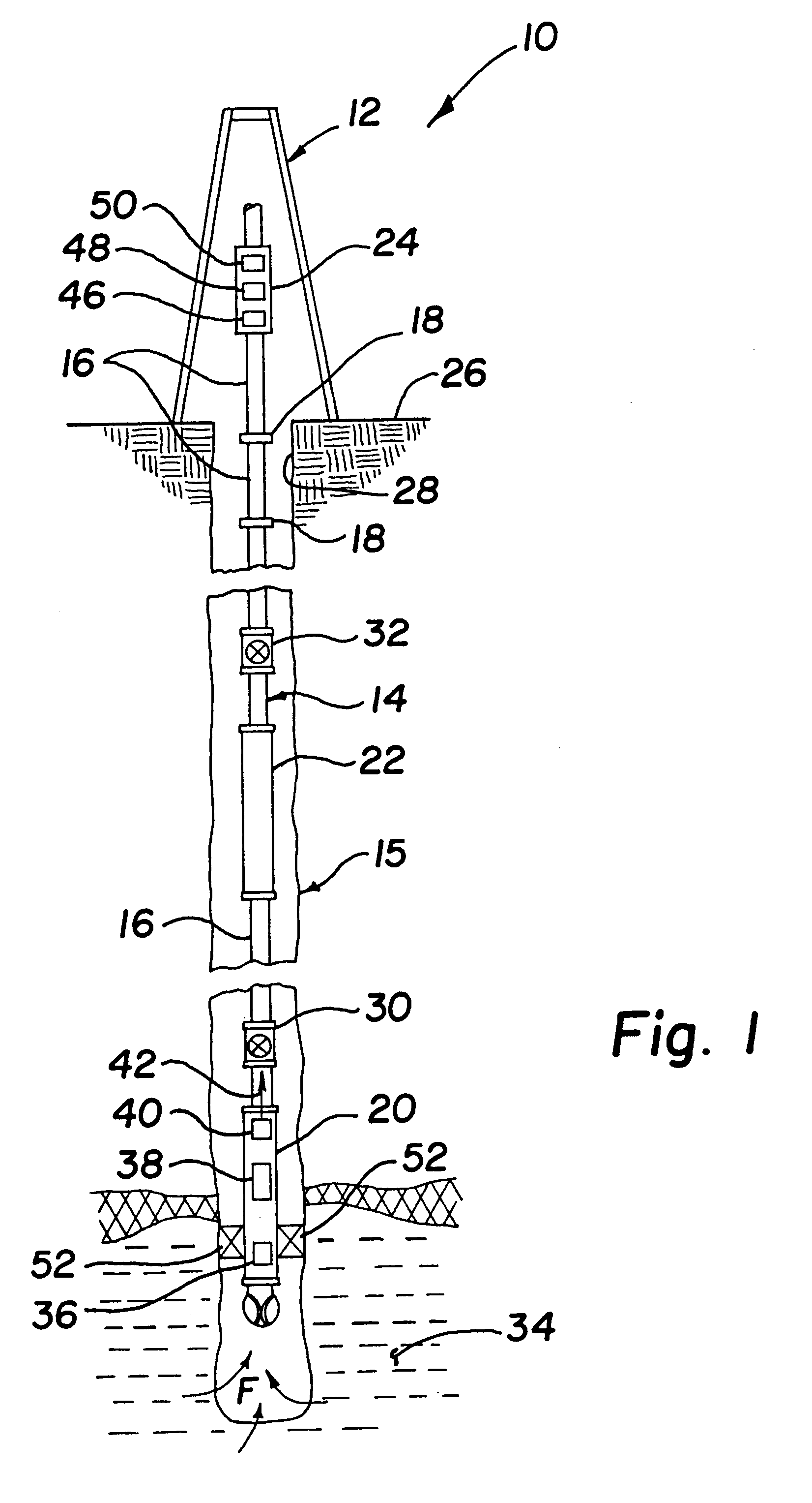
FIG. 1 is a representational view of a typical downhole drilling apparatus 10. Above ground, a drilling rig 12 operates to support and drive a drill string 14. The drill string, tubing, and the well bore, the entire well itself comprise an acoustic channel 15 through which sound waves are propagated. The drill string 14 is often made up of a plurality of pipe sections 16 connected together by tool joints 18. The drill string 14 is used for operations within a wellbore 28 which may or may not bear casing along portions of its length. Depending on the circumstances at the well site, the drill string 14 may include valves, packers, subs, collars or other upsets. FIG. 1 shows communication units 20, 22 and 24 which may be placed on, in or near the drill string 14, below, at or above the surface 26, as shown. The communication units 20, 22 and 24 may be utilized for transmitting and receiving acoustic signals to and from locations within an oil well.

The signals may correspond to test dat...


PUM


Abstract

A method and apparatus for data communication in an oil well environment, wherein the method comprises detecting an acoustic signal transmitted along an acoustic channel, the acoustic signal being distorted from transmission through the acoustic channel, generating a transmitted data signal in response to the acoustic signal, inputting the transmitted data signal to an adaptive equalizer and adaptively equalizing the transmitted data signal to produce an equalized data signal related to the transmitted data signal by a mathematical function. The detecting step may include positioning an acoustic receiver in a communication unit along the acoustic channel. The communication unit may be positioned downhole and the adaptive equalizer may be positioned remotely relative to the communication unit or may be placed in the communication unit. The adaptive equalizer may be a frequency domain filter, a neural net adaptive equalizer or a nonlinear recurrent neural net equalizer. The acoustic signal may comprise a plurality of discrete transmissions which may be a training sequence for training the adaptive equalizer and may comprise a first discrete transmission transmitted repeatedly.The method of data communication in an oil well environment may comprise the steps of transmitting an acoustic signal from a first location along an acoustic channel, detecting the acoustic signal at a second location along the acoustic channel, generating a transmitted data signal in response to the acoustic signal, inputting the transmitted data signal to an adaptive equalizer and adaptively equalizing the transmitted data signal to produce an equalized data signal related to the transmitted data signal by a mathematical function. The transmitting step may further comprise positioning an acoustic transmitter in a first communication unit along the acoustic channel downhole or elsewhere. The method may further comprise acquiring data, generating an original data signal in response to the acquired data and inputting the original data signal to the acoustic transmitter. The acoustic signal may comprise a series of acoustic training signals for training the adaptive equalizer. The acoustic training signals may be transmitted at a predetermined time. A stored training signal may include a series of stored training data signals corresponding to the series of acoustic training signals. At least a portion of the stored training signals may be cross-correlated to the transmitted data signal. The acoustic signal may comprise a notification signal for notifying the adaptive equalizer of a training session.

Description

The present invention pertains to a system for transmitting acoustic data through a tubing string.BACKGROUND OF INVENTIONThere has been much interest in transmitting acoustic signals to and from locations in an oil well environment. The basic operating principal in acoustic signal transmission in a tubular media is to impart propagating stress waves into a pipe or tubing string which travel within the pipe to a distant location where transducers detect the signal which is then interpreted by the receiving equipment. In this way, data and signals can be transmitted via mechanical tubular transmission channels such as pipe or tubing.There are many practical problems associated with using this scheme. When tubing, drill pipe or casing are used as an acoustic transmission channel, there is often significant signal distortion due to reflective interfaces in the channel such as tool joints, collars or other upsets. Additionally, there can be significant attenuation and interference associ...

Claims


Application Information

Patent Timeline
IPC IPC(8): E21B47/12E21B47/16E21B41/00
CPCE21B47/16E21B2041/0028E21B2200/22
Inventor SCHULTZ, ROGER L.
Owner WELLDYNAMICS INC
Why Eureka
Try Eureka