Circuit to test the working of at least one antenna

a technology of circuits and antennas, applied in the direction of antennas, electronic circuit testing, antenna adaptation in movable bodies, etc., can solve the problems of high probability of antenna total failure to the point of total failure, malfunction or damage of antenna feed cables, etc., and achieve the effect of little

Inactive Publication Date: 2002-08-20
NOKIA MOBILE PHONES LTD
View PDF8 Cites 95 Cited by
  • Summary
  • Abstract
  • Description
  • Claims
  • Application Information

AI Technical Summary

Benefits of technology

According to a special feature of the invention, the impedance of the secondary path consists of an elongated structure whose length, when it is a single component, for example, is of the same order of magnitude as the length of the rod antenna, or it co

Problems solved by technology

One disadvantage of selecting such a location is that the probability of damaging the antenna to the point of total failure is high the vehicle is involved in an accident or when other external forces act on the antenna.
The total failure of the antenna can have fatal consequences in a traffic accident or when the vehicle is damaged as it is not possible then to make a telephone call in order to call for help.
However, malfunctions or damage to the antenna feed cable leading to the emergency antenna can arise when operating the vehicle or connecting the antenna during the manufacture of the vehicle that remain undetected because the emergency antenna is not used during normal operation.
Under certain circumstances, this antenna may not work properly in an emergency.
Additionally, its efficiency is generally lower that that of the main antenna when installed in the interior of the vehicle.
This may also lead to the inability to connect to the base station u

Method used


Image

  • Circuit to test the working of at least one antenna
  • Circuit to test the working of at least one antenna
  • Circuit to test the working of at least one antenna

Examples


Embodiment Construction

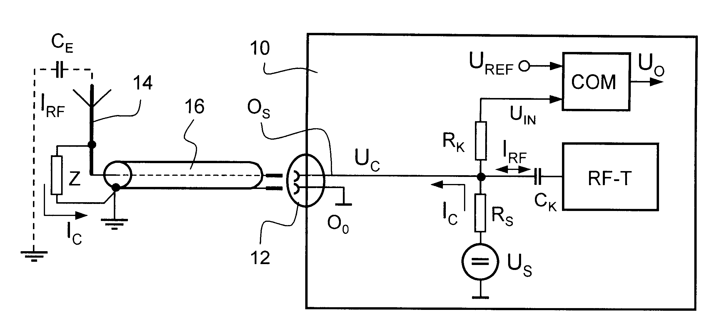
A radio telephone 10 has, as shown in FIG. 1, a transceiver RF-T. The transceiver is connected via antenna connection 12 to an antenna 14, which is preferably designed as an external antenna and which is mounted on the roof of a vehicle (not shown). An antenna wire 16, in the present case a coaxial cable that is generally installed under the interior paneling of the vehicle, connects the antenna 14, which is located a distance from the radio telephone 10, to the antenna connection 12. Faults and damage to the antenna wire 16 and to the antenna connection 12 resulting from the hidden installation are difficult to detect visually. Antenna connection 12 contains a signal contact O.sub.S and a ground contact O.sub.O.

In this example the antenna 14 is the well-known vertical pole radiator with a length of almost one-fourth of the transmission wavelength .lambda. of the transceiver signal. The antenna wire 16 is connected to the lower end of the radiator. The other end projects into space ...


PUM


Abstract

A circuit to test the working of antennas for a radio telephone. The antennas each have a radiator with one end that open rises up into the space. The test currents flow through antenna wires to the antennas independent of a signal current (IRF). A secondary path with an impedance that is parallel to the RF path is connected to each radiator to return the separate test currents. A voltage evaluator monitors the operating state of the antennas by comparing the test voltages induced by the test currents at the antenna connections with a reference value and generates corresponding indication signals that provide information on the operating state of the antennas.

Description

The invention pertains to a circuit to test the working of an antenna, especially an antenna for a radio telephone that has more than one antenna. The invention allows the radio telephone to detect a malfunction in the antenna wire or detect a missing, incorrectly mounted or failed vehicle antenna, for example as the result of damage from an accident, at any time and to automatically switch to a operative antenna.Due to the fact that a radio telephone only works when all components of the communication system work and that antennas are often mechanically sensitive due to their location, the solution according to the invention significantly increases the reliability of a radio telephone in an emergency.Telephones in vehicles are usually equipped with an external or window mounted antenna. The location of this antenna is primarily determined by the requirements that need to be met to achieve optimal transmitting quality.One disadvantage of selecting such a location is that the probabi...

Claims


Application Information

Patent Timeline
IPC IPC(8): H01Q3/26H01Q1/32
CPCH01Q1/32H01Q3/267
Inventor FRITZMANN, MARTINWAGNER, THOMAS
Owner NOKIA MOBILE PHONES LTD
Why Eureka
Try Eureka