Workpiece loader/unloader system

a workpiece and robot technology, applied in the field of loader/unloader system, can solve the problems of insufficient time delay, damage to the workpieces transported by the loader/unloader robot, and potential damage to the robots themselves, so as to reduce the overall cost of the loader/unloader system

Inactive Publication Date: 2002-08-27
VALIANT CO LTD
View PDF2 Cites 13 Cited by
  • Summary
  • Abstract
  • Description
  • Claims
  • Application Information

AI Technical Summary

Benefits of technology

A still further advantage of the present invention is that, since the loader manipulator is used not only to load unmachined parts into the work station but also to mechanically push the shuttle with its completed workpiece away from the work station, only a single robotic manipulator is required to perform both the load and unload operations. This, in turn, significantly reduces the overall cost of the loader / unloader system.
is that, since the loader manipulator is used not only to load unmachined parts into the work station but also to mechanically push the shuttle with its completed workpiece away from the work station, only a single robotic manipulator is required to perform both the load and unload operations. This, in turn, significantly reduces the overall cost of the loader / unloader system.

Problems solved by technology

It is, of course, imperative that the loader robot avoid collision, or any possible collision, with the unloader robot at all times. Any such collision between the loader and unloader robots, or the parts which they transport, would result in damage not only to the workpieces transported by the loader and / or unloader robots, but also potentially damage the robots themselves.
This robot sequencing in the time results in a time delay of several seconds sufficient to terminate operation of either the loader or unloader operation in the event of a system jam or other malfunction and still avoid a collision between the loader and unloader robots.
One disadvantage is that the loader and unloader robots are expensive both in acquisition and operating costs.
Furthermore, the necessity of having both a separate loader robot and unloader robot for each machine significantly increases the overall cost of performing the machining operation.
A still further disadvantage of these previously known loader and unloader robotic systems is that the part exchange operation necessarily consumes several seconds more than an unflexible transfer system, typically about five seconds, after each machining operation to ensure that the loader and unloader robots do not collide together.
This, however, necessarily lengthens the cycle time for the machining operation by several seconds.

Method used


Image

  • Workpiece loader/unloader system
  • Workpiece loader/unloader system
  • Workpiece loader/unloader system

Examples


Embodiment Construction

Embodiment of the Present Invention

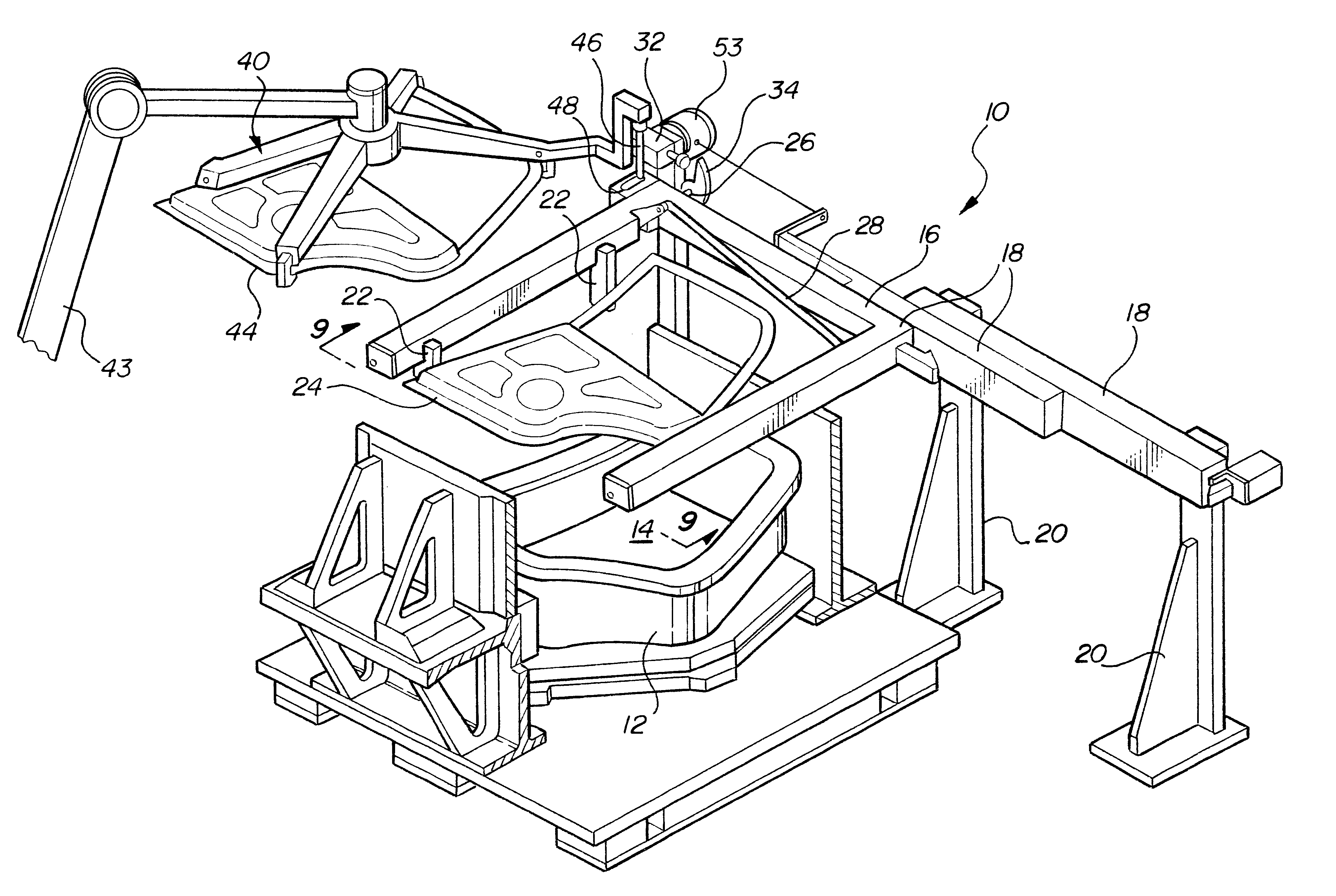
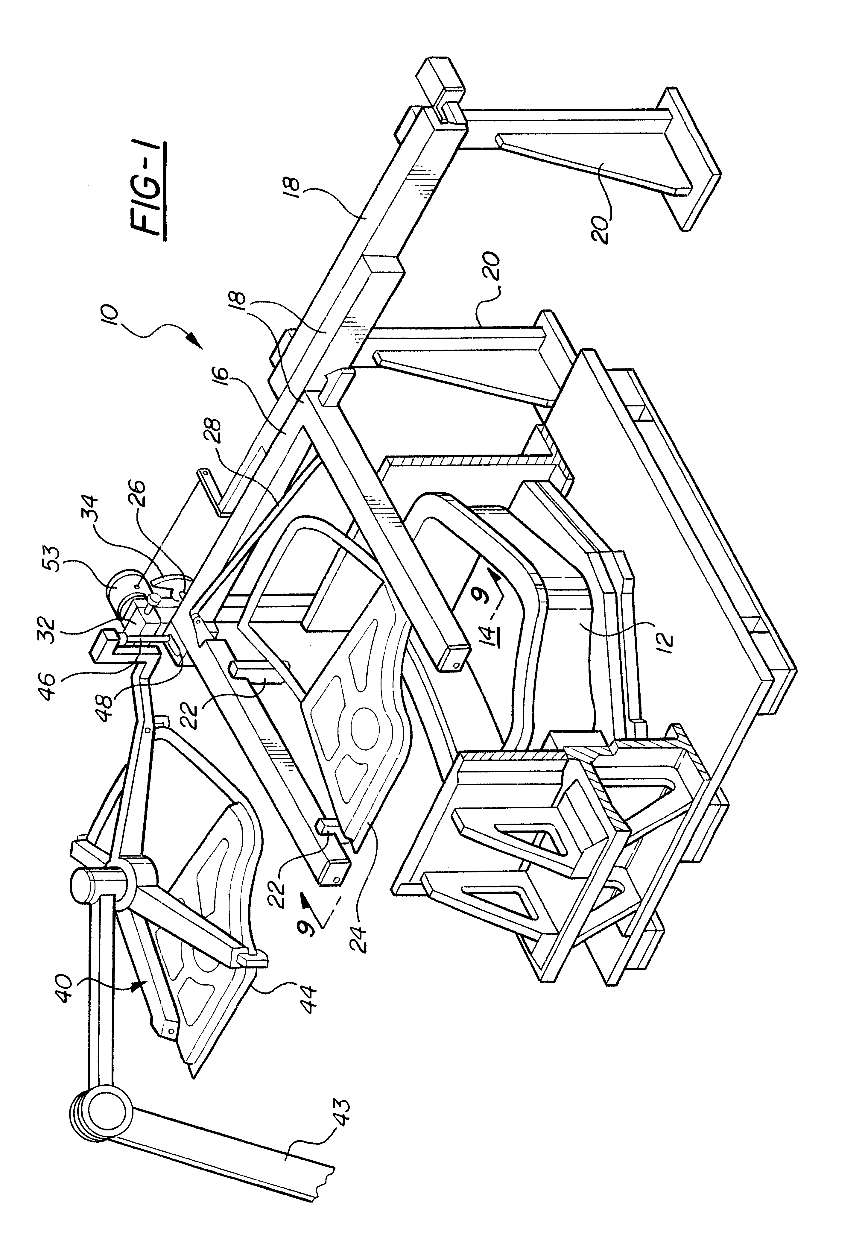
With reference first to FIG. 1, a preferred embodiment of the loader / unloader system 10 of the present invention is there shown for use with an industrial machine 12, such as a hemming machine. The machine 12, in the conventional fashion, includes a work station 14. Unmachined workpieces are positioned at the work station 14, machined, and then returned from the work station 14 as finished machine workpieces.

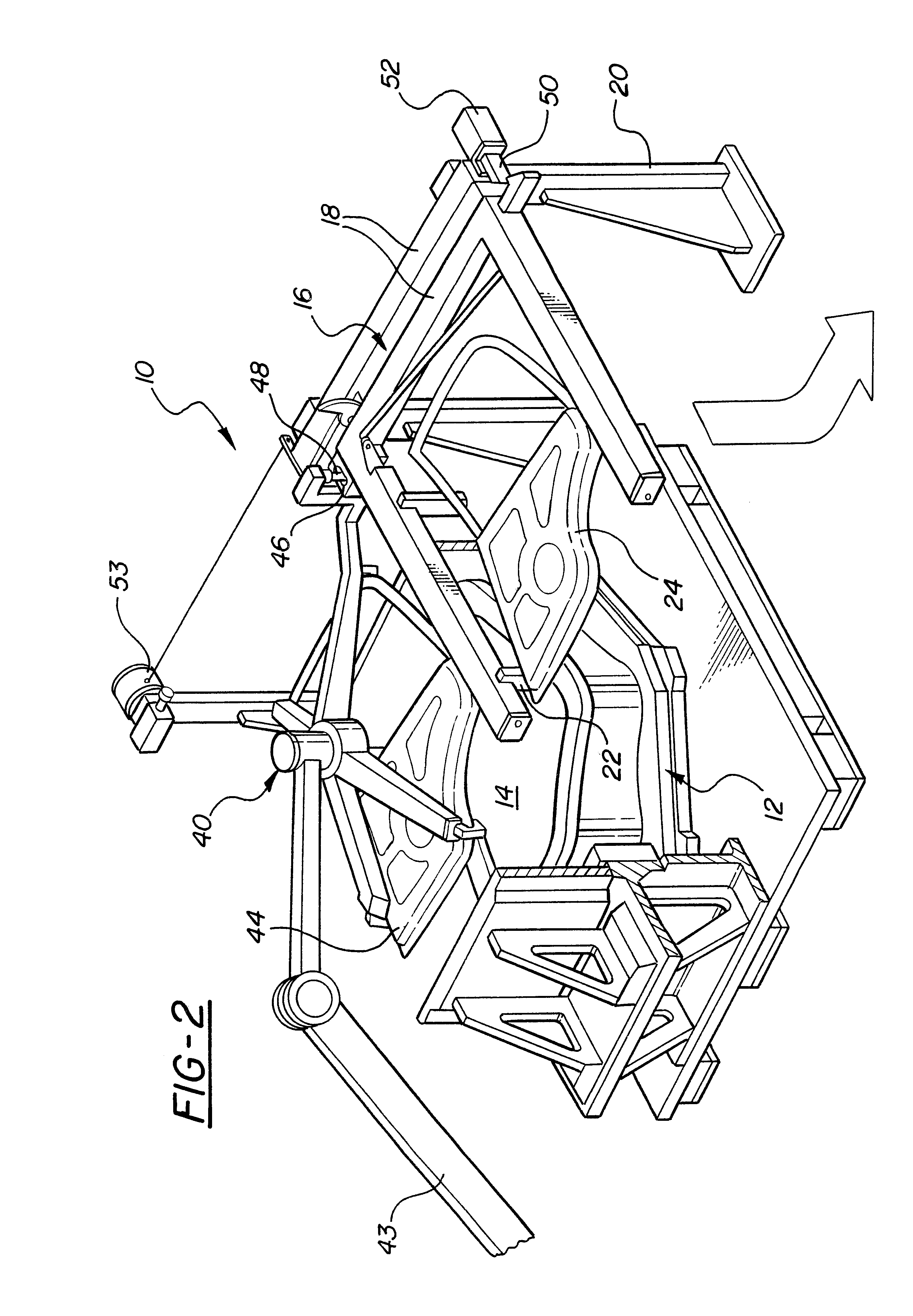
Referring to FIGS. 1 and 2, the system 10 of the present invention comprises a shuttle 16 which is laterally movable between an extended position, illustrated in FIG. 1, and a retracted position, illustrated in FIG. 2. Any conventional means may be employed to allow the shuttle to move between its extended position and retracted position. However, in the preferred embodiment of the invention, the shuttle 16 is mounted by telescopic slides 18 to stationary frame members 20.

The shuttle 16 is generally U-shaped and, when in its extended position, ...


PUM

PropertyMeasurementUnit
movementaaaaaaaaaa
timeaaaaaaaaaa
time delayaaaaaaaaaa

Abstract

A workpiece loader / unloader system for an industrial machine, such as a hemmer, is disclosed. The system includes a single pocket shuttle movable between an extended position in which the shuttle overlies a work station on the industrial machine, and a retracted position in which the shuttle is laterally spaced from the work station. A gripper on the shuttle selectively engages and supports the workpiece after the workpiece has been machined at the work station. A loader manipulator is movable between a preload position in which the loader supports an unmachined workpiece at a position laterally spaced from the work station, and a load position in which the loader manipulator overlies the work station. An actuator moves the loader manipulator between the preload and load position. Furthermore, the loader manipulator mechanically engages the shuttle and simultaneously moves the shuttle from its extended position and to its retracted position as the loader manipulator moves from its preload and to its load position. A passive system, such as a spring, returns the shuttle from its retracted and to its extended position.

Description

I. Field of the InventionThe present invention relates generally to a loader / unloader system for use with an industrial machine, such as a hemming machine.II. Description of the Prior ArtMany industrial machines, such as hemming machines, include a work station adapted to receive an unmachined part whereupon the machine performs its particular machining operation. Following the machining operation, the now machined workpiece is removed from the work station and replaced by an unmachined workpiece whereupon the entire operation is repeated.Most industrial applications utilize both a loader robot for moving unmachined parts from inventory and into the work station on the machine. Similarly, an unloader robot is then utilized to remove the finished workpieces following the machining operation from the work station. Typically, conventional conveyor systems supply the loader robot with unmachined workpieces while, similarly, conventional conveying systems remove the machined workpieces f...

Claims


Application Information

Patent Timeline
Patent Type & Authority Patents(United States)
IPC IPC(8): B21D43/10B21D39/02B21D43/04
CPCB21D39/021B21D43/105
Inventor BAULIER, DOMINIQUE
Owner VALIANT CO LTD
Why Eureka
Try Eureka