
Linear motor

a linear motor and motor body technology, applied in the direction of dynamo-electric machines, electrical apparatus, structural associations, etc., can solve the problems of difficult to obtain a high thrusting force, difficult to design a linear motor small and light, and difficult to detect with a high precision

Inactive Publication Date: 2002-08-27
SANKYO SEIKI MFG CO LTD
View PDF2 Cites 24 Cited by
  • Summary
  • Abstract
  • Description
  • Claims
  • Application Information

AI Technical Summary

Benefits of technology

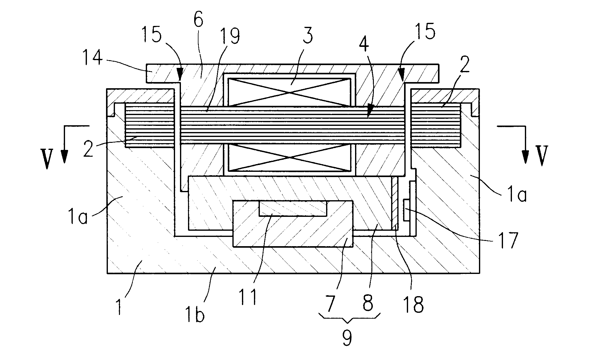
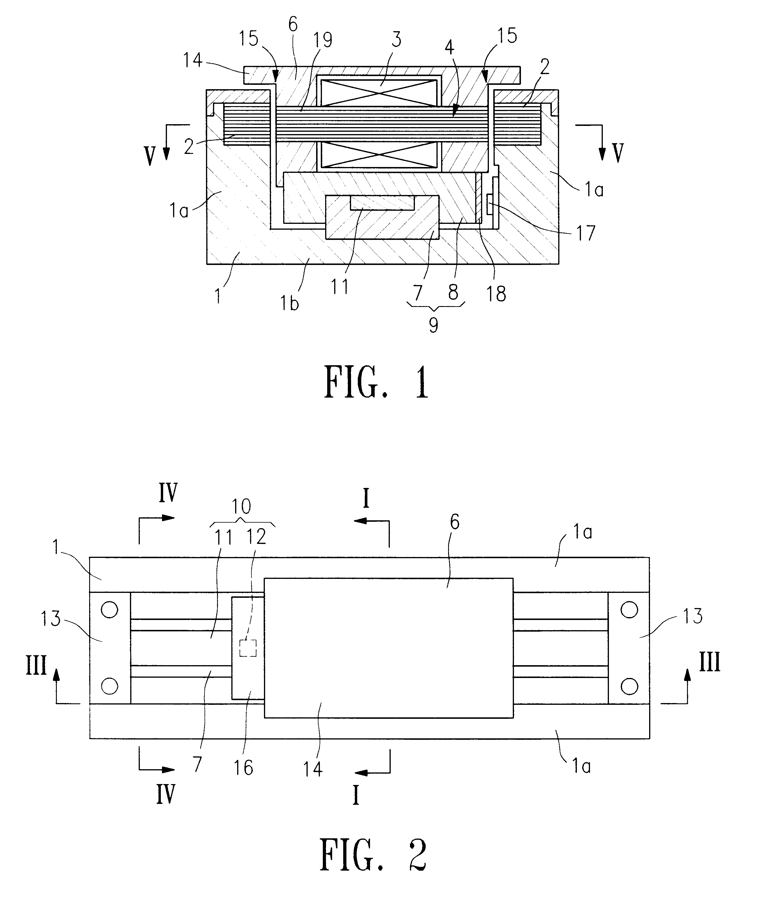
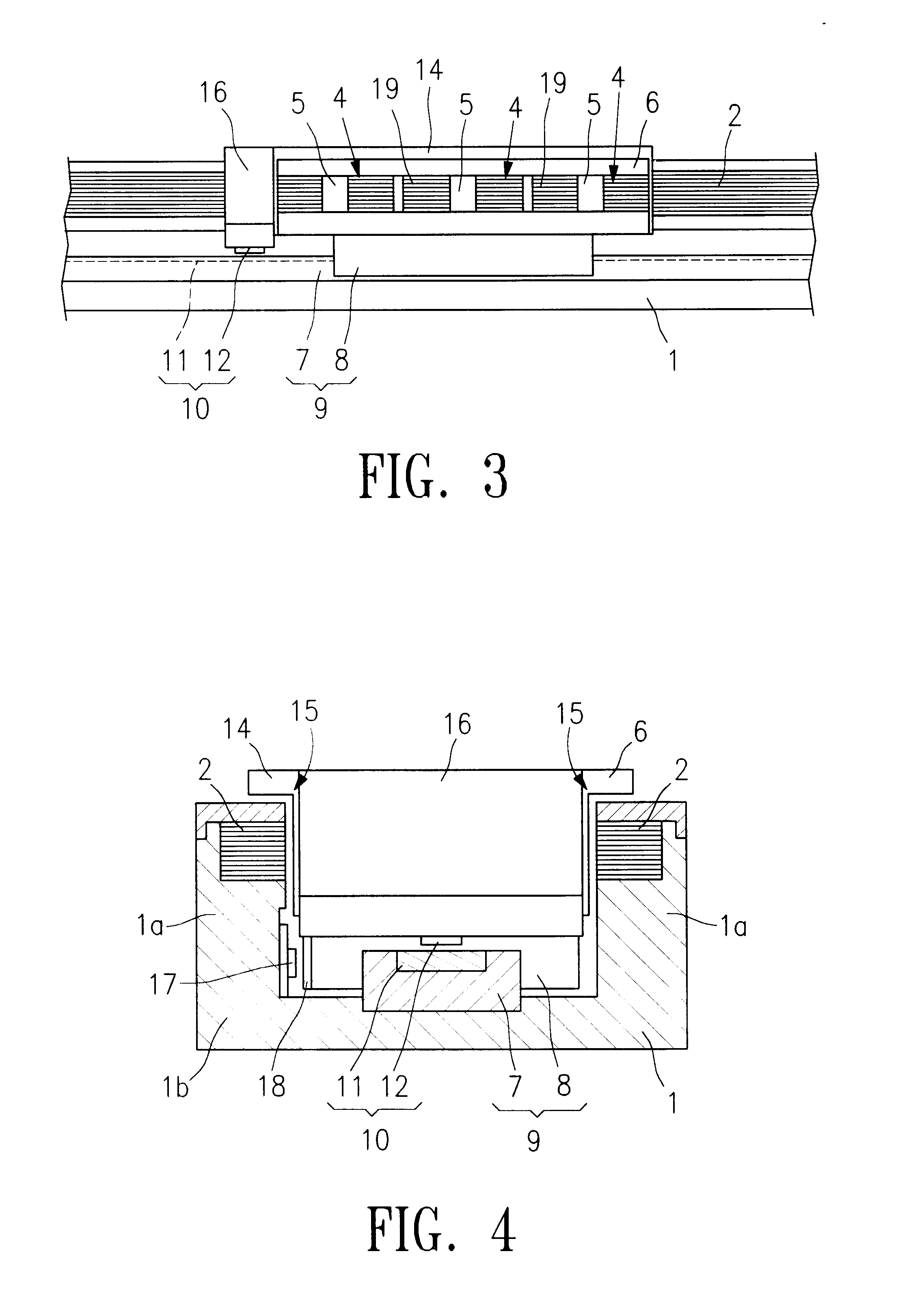
In accordance with one embodiment of the present invention, a linear guide and an armature-side block are disposed within a channel-shaped frame, and a linear encoder can be provided on or adjacent the linear guide. Accordingly, variations in the gap between the linear scale and the position detection sensor are difficult to take place when the linear motor is driven. In other words, the gap management is easy. Also, the linear encoder can be disposed in an area that is difficult to receive influences of leak magnetic fluxes of the main body of the linear motor, and thus a high accurate position detection can be conducted.
In accordance with one embodiment of the present invention, two linear guides are disposed on a frame and an armature-side block is mounted over the two linear guides. As a result, relative movements between the frame and the armature-side block are stabilized.

Problems solved by technology

This is an obstacle to designing a smaller and lighter linear motor.
Also, since the magnetic circuit has a single opposing surface 104, it is difficult to obtain a high thrusting force.
As a result, the position detection with a high precision becomes difficult, and dust and particles more likely affect the sensors.
Moreover, the sensors become more vulnerable to mechanical external disturbances.
Accordingly, variations in the gap between the linear scale and the position detection sensor are difficult to take place when the linear motor is driven.

Method used


Image

  • Linear motor
  • Linear motor
  • Linear motor

Examples


first embodiment

The first embodiment described above is one of preferred embodiments of the present invention, and the present invention is not limited to the embodiment described above. A variety of modifications can be made within the scope of the subject matter of the present invention. For example, in the embodiment described above, the linear scale 11 of the linear encoder 10 is embedded in the rail 7 of the linear guide 9. However, the linear scale 11 may be adhered to the surface of the rail 7, as shown in FIG. 7.

A linear motor in accordance with a second embodiment of the present invention is described with reference to the accompanying drawings. It is noted that structural elements of the second embodiment that are the same as those of the first embodiment are indicated by the same reference numbers.

FIGS. 8 through 11 show a linear motor in accordance with the second embodiment of the present invention. The linear motor includes a frame 1 linearly extending in a longitudinal direction ther...

second embodiment

In the second embodiment, the armature-side block 6 functions as a mover, and the two linear guides 9 guide the movement of the armature-side block 6. Accordingly, the right side and the left side of the armature-side block 6 in its width direction are more balanced compared to an armature-side block that is guided by a single linear guide. As a result, more stabilized movements of the armature-side block 6 are obtained even when the center of gravity of an object to be moved is offset either to the right side or to the left side.

In the embodiment described above, the cores 2 are disposed on two side walls 1a of the frame 1 and the two linear guides 9 are disposed on the bottom plate 1b of the frame 1. However, as shown in FIGS. 12-15, the linear guides 9 may be disposed on the two side walls 1a of the frame 1, and the cores 2 may be disposed on the bottom plate 1b of the frame 1. It is noted that the elements shown in FIGS. 12-15 that are the same as those of the linear motor shown...


PUM


Abstract

A linear motor includes a frame linearly extending in a longitudinal direction and having a channel-shaped cross section. The frame has sidewalls and a bottom wall that define a channel. A core is disposed on each of the side walls of the frame. An armature-side block is disposed in the channel of the frame. The armature-side block has a plurality of armatures, each of the armatures having two end surfaces at positions opposing to the cores provided on the side walls of the frame. One linear guide is disposed between the frame and the armature-side block. The linear guide has a rail fixed to the bottom wall of the frame and a slide block fixed to the armature-side block, such that one of the frame and the armature-side block is linearly movable relative to the other. A linear encoder having a linear scale and a sensor spaced a distance from the linear scale are disposed within the channel of the frame.

Description

1. Field of the InventionThe present invention relates to linear motors. More particularly, the present invention relates to linear motors that are suitable to be used for FA (factory automation).2. Description of Related ArtA typical conventional linear motor has a mover 101 and a stator 102. Two linear guides 103 are mounted on the stator 102, and the mover 101 is mounted in a manner moveable along the stator 102, as shown in FIG. 16. A magnetic circuit is provided to generate a thrusting force to the mover 101. A surface 104 of the magnetic circuit opposing to the mover 101 is disposed between the two linear guides 103. In other words, the magnetic circuit has a single opposing surface 104, which is formed between the two linear guides. Also a variety of sensors 105 such as linear encoders and the like are disposed to detect the position of the mover 101. The sensors 105 are mounted on an exterior side surface of the linear motor or other exterior surfaces outside the linear moto...

Claims


Application Information

Patent Timeline
Patent Type & Authority Patents(United States)
IPC IPC(8): H02K41/02H02K29/06H02K11/00
CPCH02K41/033H02K11/0026H02K29/06H02K11/22
Inventor SHIMURA, YOSHIKI
Owner SANKYO SEIKI MFG CO LTD
Learn More