Cruciform parachute with arms attached

a technology of cruciform or cross-sectional parachutes and arms, which is applied in the field of parachutes, can solve the problems of long time constant of pendulum motion once initiated, increase the cost of equipment, so as to overcome the stability and oscillation problems

Inactive Publication Date: 2002-09-03
AIRBORN SYST NORTH AMERICA OF NJ INC
View PDF23 Cites 17 Cited by
  • Summary
  • Abstract
  • Description
  • Claims
  • Application Information

AI Technical Summary

Benefits of technology

The primary purpose of the present invention is to overcome the problems associated with known cruciform or cross parachutes, including the cruciform parachute of the '695 patent. The improved crucifo

Problems solved by technology

A major drawback of the cruciform parachute configuration, however, is the relatively large pendulum oscillation about the vertical, on the order 10.degree. to 15.degree., and other stability problems associated with this design.
While these changes increase the stability and the drag coefficient of cruciform parachutes, they introduce new drawbacks, such as excess weight, bulk and costs, and the longer time constant of pendulum motion once initiated.
However, as the porosity/permeability of the canopy fabric is decreased, stability is also decreased, and other problems such as opening shock are encountered.
Thus, it has not been previously possible to utilize zero or near zero porosity materials in cruciform parachutes because

Method used


Image

  • Cruciform parachute with arms attached
  • Cruciform parachute with arms attached
  • Cruciform parachute with arms attached

Examples


Embodiment Construction

Although only three preferred embodiments of the invention are explained in detail, it is to be understood that the embodiments are given by way of illustration only. It is not intended that the invention be limited in its scope to the details of construction and arrangement of components set forth in the following description or illustrated in the drawings. Also, in describing the preferred embodiments, specific terminology will be resorted to for the sake of clarity. It is to be understood that each specific term includes all technical equivalents which operate in a similar manner to accomplish a similar purpose.

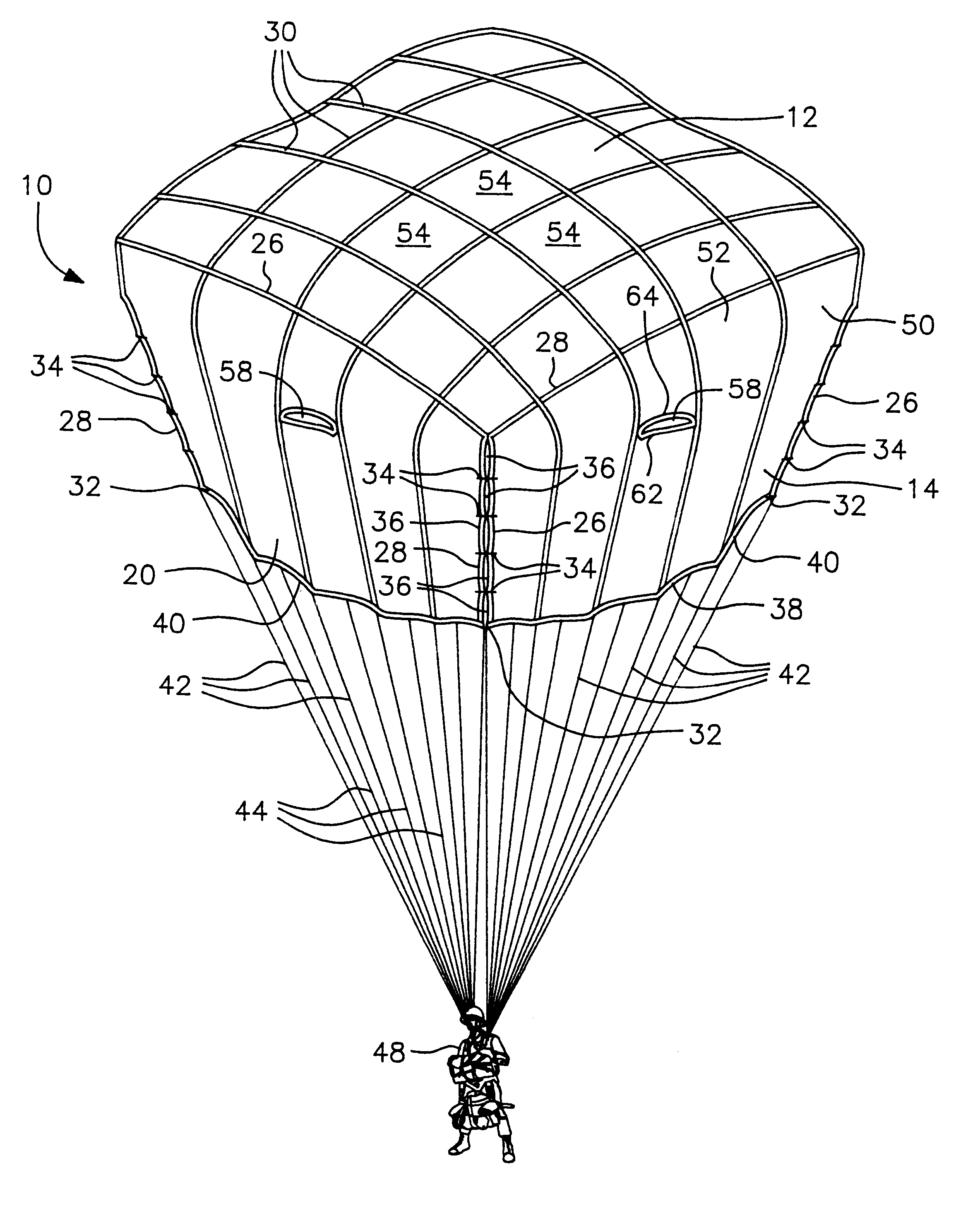
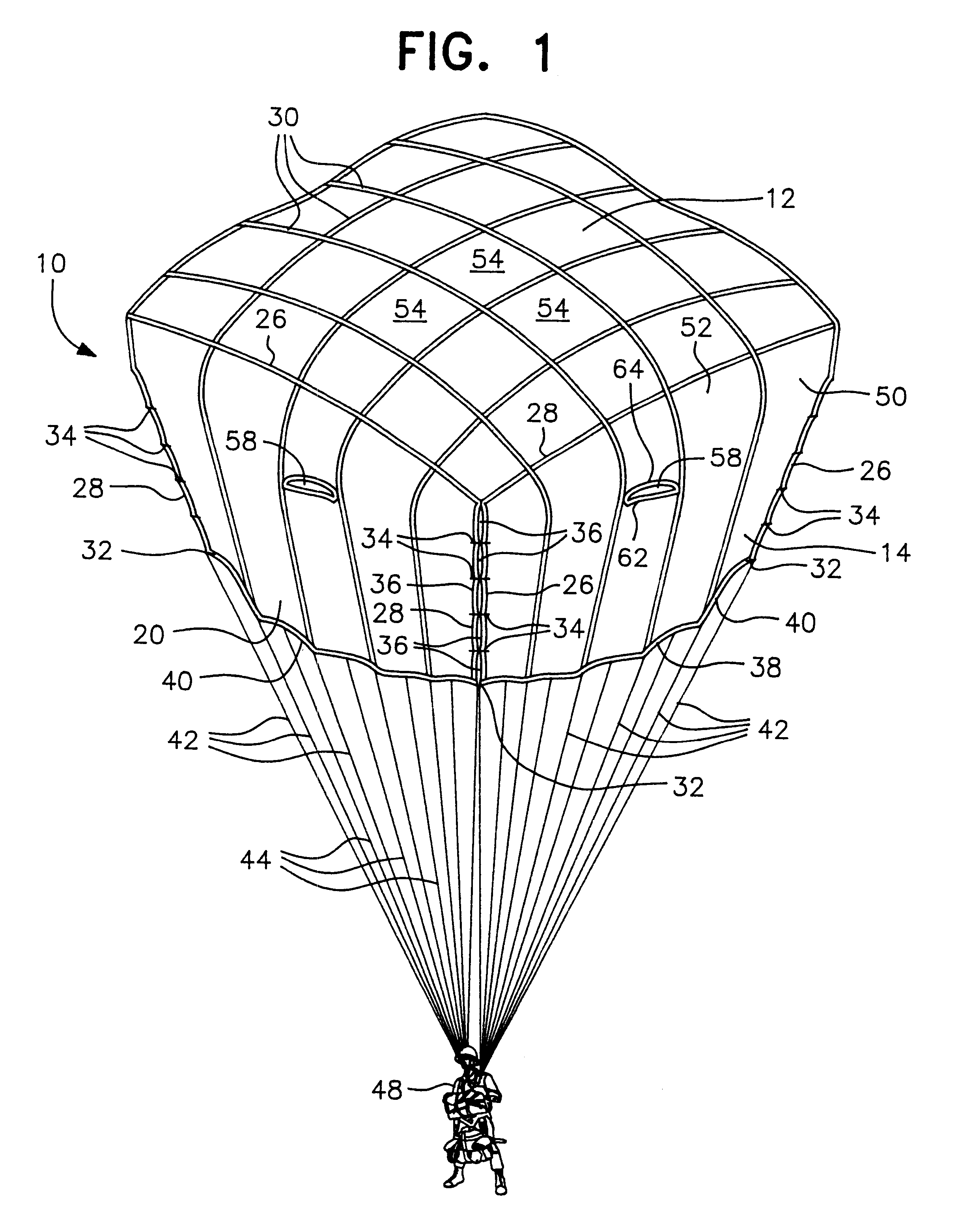
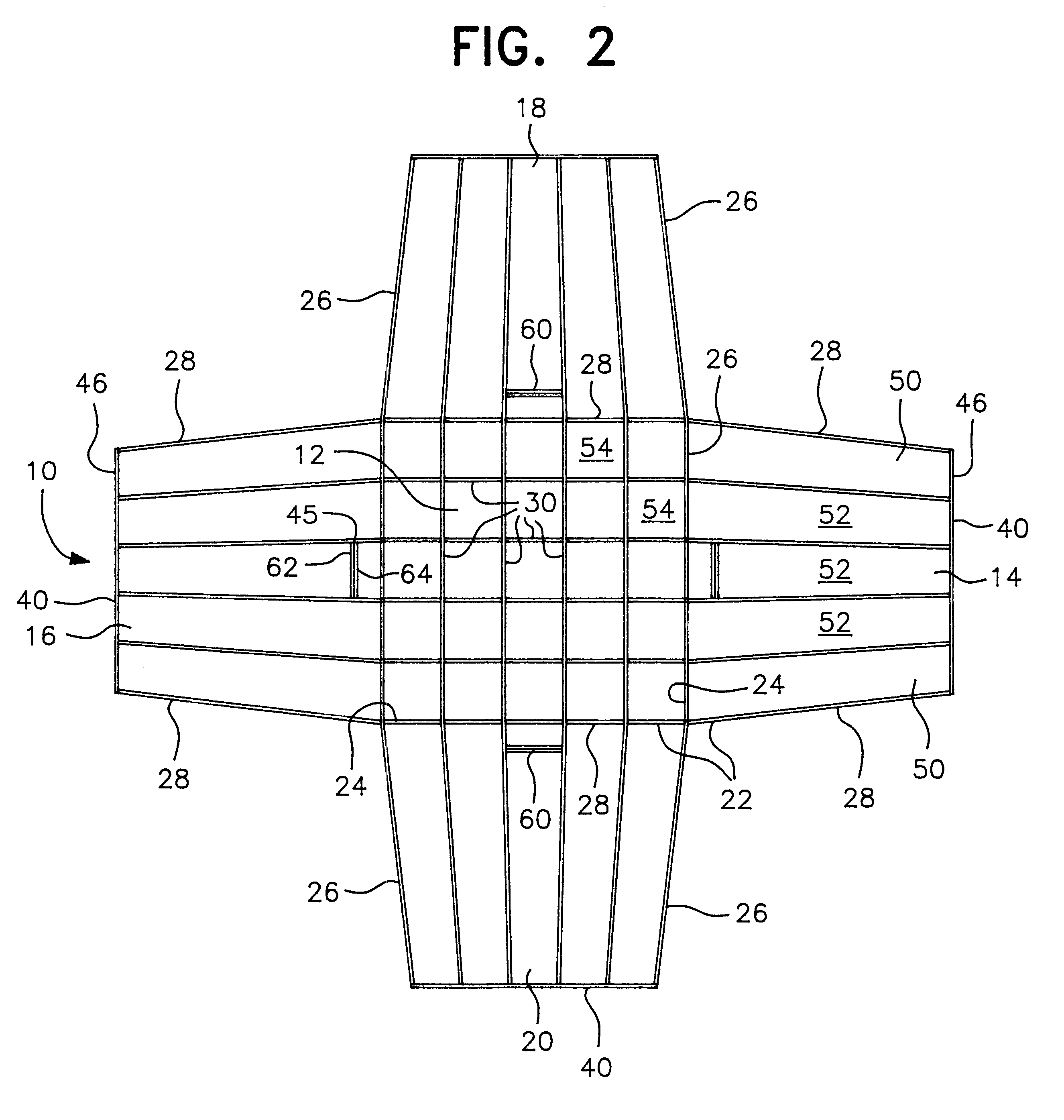
As shown in the drawings, the parachute of this invention has a canopy of cruciform or cross shape generally designated by reference numeral 10 in FIGS. 1-4 and by reference numeral 110 in FIGS. 5-6. In FIGS. 1-4, the canopy 10 includes a substantially square crown or central section 12 and four laterally extending wings or arms 14, 16, 18, and 20. Each lateral arm is atta...


PUM


Abstract

An improved cruciform or cross parachute is formed by attaching the adjacent edges of the lateral arms to each other to form a three-dimensional canopy, when inflated, which is substantially square at the top and substantially round at the lower edge. The attachment of the adjacent edges of the arms are such as to provide generally vertical openings or vents through which air can flow outwardly from underneath the canopy, which form "corner air flow jets", thus allowing use of zero or near zero porosity fabric for constructing the canopy. Attachment of the adjacent edges of the arms at their outer tips forms a continuous hem at the lower edge of the canopy which eases packing and improves reliability. Arm air flow jets of U.S. Pat. No. 5,839,695 may also be included in addition to the corner air flow jets formed by attaching the adjacent arm side edges. Air flow from underneath the canopy through the air flow jets should be sufficient to achieve a degree of flight stability for the parachute of .+-.5.degree., or less, when using a zero or near zero porosity fabric for the canopy.

Description

BACKGROUND OF THE INVENTION1. Field of the InventionThis invention relates in general to parachutes and more specifically to cruciform or cross parachutes. The present invention is a modification of the conventional cruciform parachute design, in which the arms are connected to form a parachute canopy configuration which is substantially square at the top and round at the lower edge.2. Description of the Prior ArtGenerally speaking, there are three types of parachute designs for personnel and cargo which are deployed from airborne aircraft. First, there is the conventional generally hemispherical canopy with the suspension or rigging lines connected around a continuous circular lower edge of the canopy. Second is the ram air type parachute with upper and lower surfaces generally in the shape of an airfoil with the suspension lines connected to the bottom surface. And, finally, there is the cruciform or cross parachute in which the canopy includes a generally square crown or center s...

Claims


Application Information

Patent Timeline
IPC IPC(8): B64D17/00B64D17/02
CPCB64D17/02
Inventor BERLAND, JEAN C.
Owner AIRBORN SYST NORTH AMERICA OF NJ INC
Why Eureka
Try Eureka