Bus bar wiring plate body for electric coupling box

a wiring plate body and electric coupling box technology, applied in the direction of printed element electric connection formation, coupling device connection, laminated bus-bars, etc., can solve the problems of signal leakage, reduced packaging density within and larger size of the electric coupling box itsel

Inactive Publication Date: 2002-09-03
YAZAKI CORP
View PDF11 Cites 11 Cited by
  • Summary
  • Abstract
  • Description
  • Claims
  • Application Information

AI Technical Summary

Problems solved by technology

When this leak current flows, there arise problems in that a failure caused by signal leakage may occur, and that an unexpected failure likely occurs due to the carbonization of the insulating substrate 2 caused by the heat.
However, each of such countermeasures has a problem that the size of the electric coupling box itself becomes larger and the packaging density within the electric coupling box reduces.
Further, although the bus bar members 3 are wired within groove portions formed by the respective ribs 2A on the surface of the insulating substrate 2, since both the bus bar members and the ribs are hard, it is difficult to fit the bus bar members 3 within the groove portions in a firmly fitting state.
Thus, there arises a problem that when the bus bar members 3 are not engaged by a particular engagement means, the close adhesion between both the bus bar members and the ribs can not be guaranteed and so abnormal sound such as rattling sound is generated due to the loose fitting state of the bus bar members 3.
However, the bus bar wiring plate 1 can not be miniaturized nor lightened and further is limited in the improvement of the withstand voltage.

Method used


Image

  • Bus bar wiring plate body for electric coupling box
  • Bus bar wiring plate body for electric coupling box
  • Bus bar wiring plate body for electric coupling box

Examples


Embodiment Construction

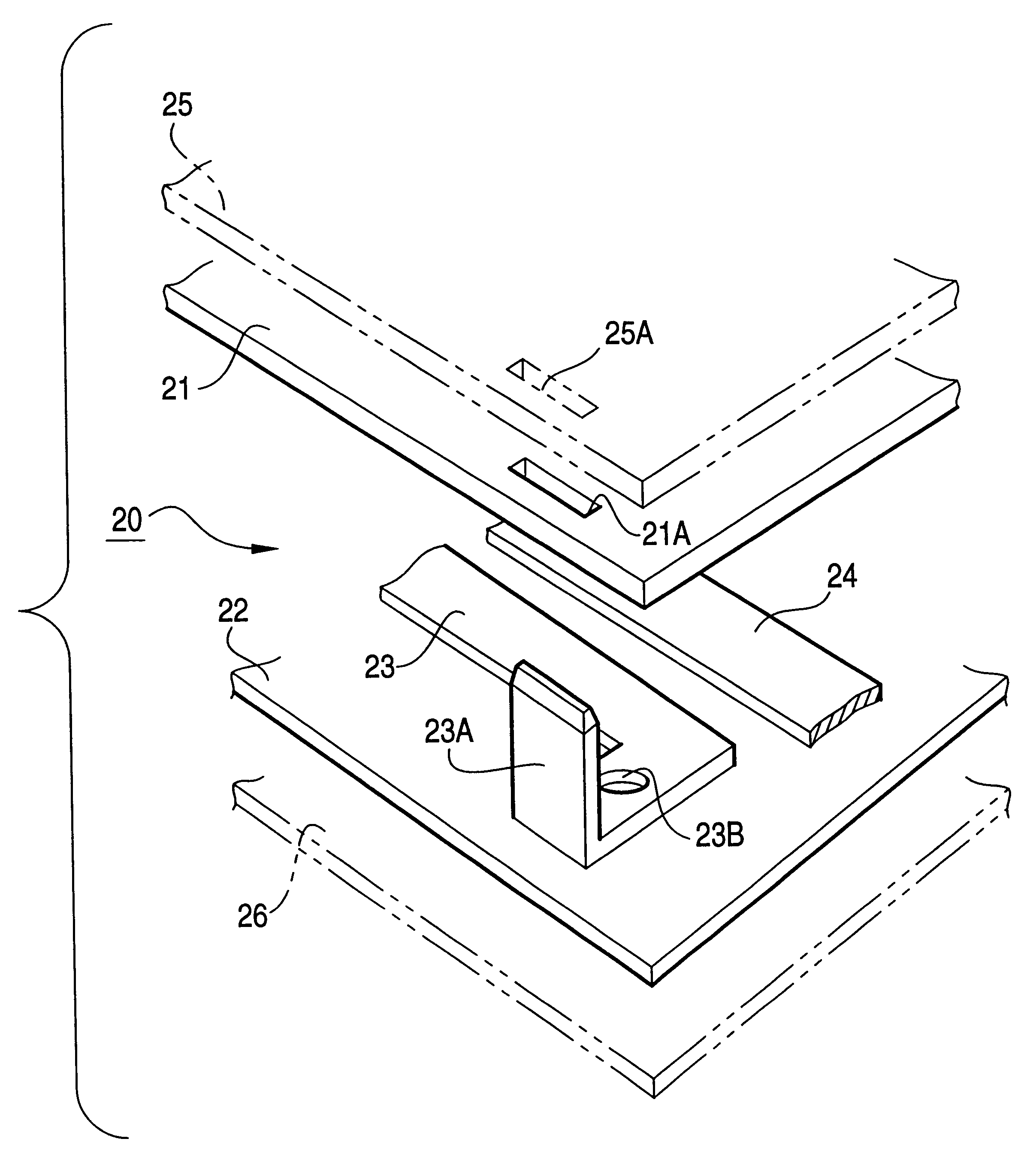
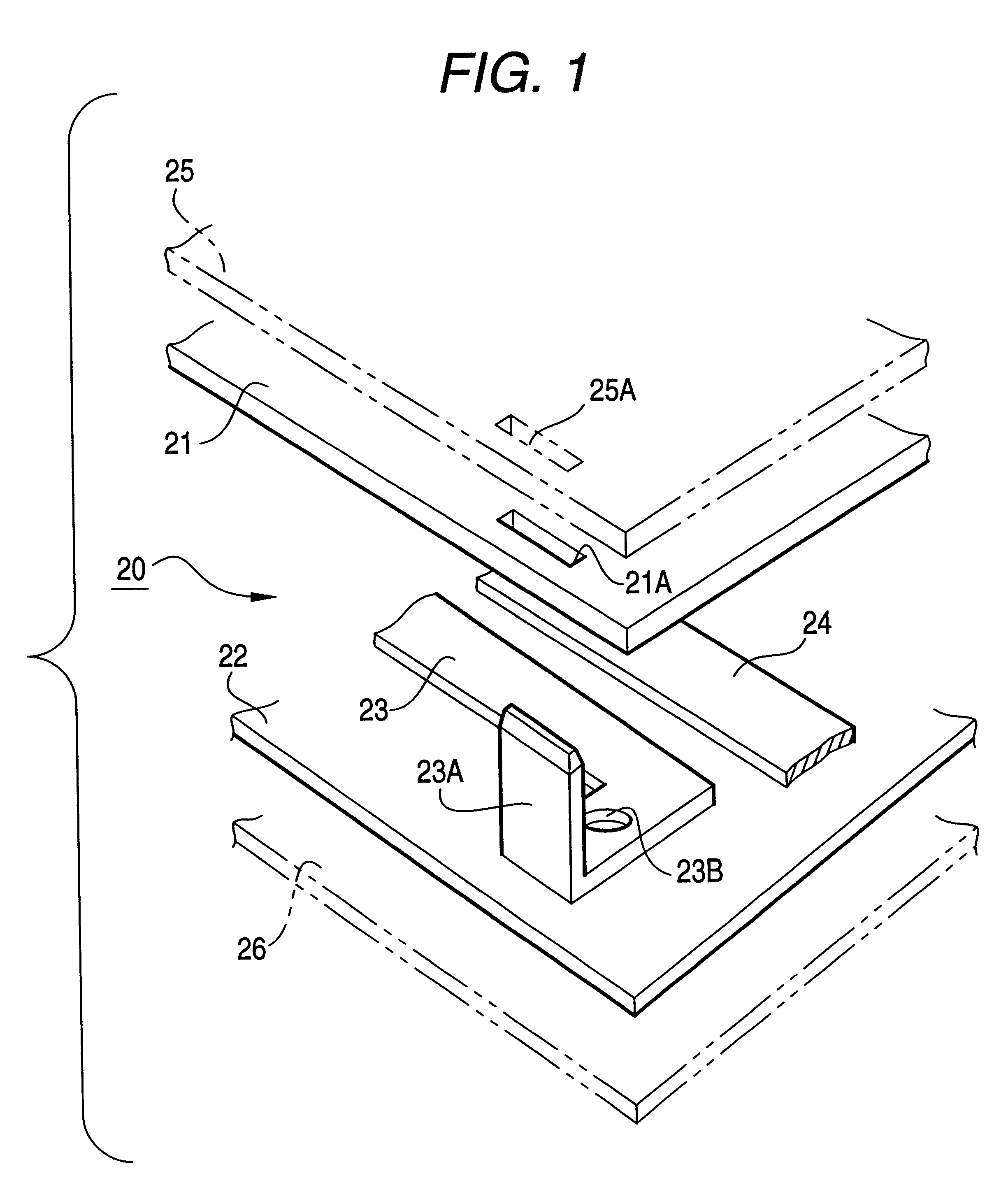
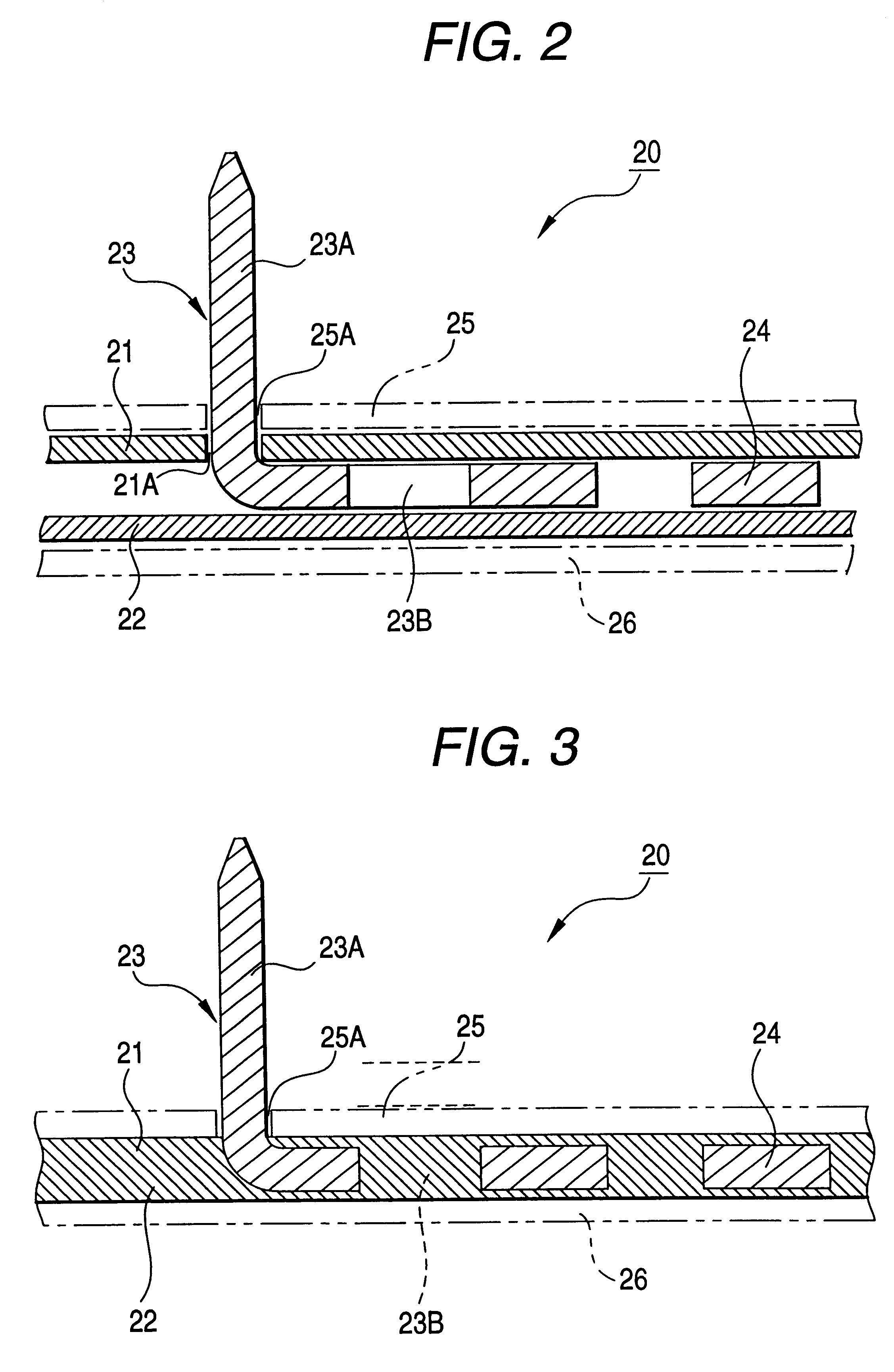
The bus bar wiring plate body for an electric coupling box according to an embodiment of the invention will be explained in detail with reference to FIGS. 1 to 3. FIG. 1 is an exploded perspective view showing the bus bar wiring plate body for an electric coupling box according to the embodiment. FIG. 2 is a sectional view showing a state where the bus bar wiring plate body of FIG. 1 has not been laminated yet. FIG. 3 is a sectional view showing a state where the bus bar wiring plate body of FIG. 2 has been laminated.

As shown in FIG. 1, a bus bar wiring plate body 20 for the electric coupling box according to the embodiment is arranged in a manner that bus bar members 23, 24 wired along a predetermined circuit are putted between two pre-hardening epoxy resin plates 21, 22 with soft properties which are disposed at upper and lower positions, respectively. Thus, when the bus bar wiring plate body is subjected to the heat pressing procedure in the not entirely laminated state shown in ...


PUM

PropertyMeasurementUnit
heat temperatureaaaaaaaaaa
temperatureaaaaaaaaaa

Abstract

A bus wiring plate body (20), for an electric coupling box, is arranged in a manner that bus bar members (23, 24) are wired between pre-hardening epoxy resin plates (21, 22) and these pre-hardening epoxy resin plates are subjected to a heat pressing process to thereby integrate the pre-hardening epoxy resin plates (21, 22) and the bus bar members (23, 24) in a laminated state. When hardened epoxy resin plates (25, 26) are disposed outside of the pre- hardening epoxy resin plates (21, 22), respectively, the strength of the bus bar wiring plate body (20) can be improved. Thus, since the bus bar members (23, 24) are sealed in an insulated state, leak current is reduced. Further, the thickness of the bus bar wiring plate body (20) is reduced to a large extent, so that the electric coupling box can be miniaturized and lightweighted.

Description

1. Technical Field of the InventionThe present invention relates to a bus bar wiring plate body for an electric coupling box used for coupling an electric system within a vehicle such as an automobile etc. and, more particularly, relates to the configuration of a bus bar wiring plate body for an electric coupling box which increases the insulating resistance between bus bar members disposed within the electric coupling box to make it possible to improve and withstand voltage and reduce leak current.2. Related ArtAs shown in FIG. 7, a related electric coupling box such as a junction block (J / B), a relay box etc. used for electric wiring within a vehicle such as an automobile etc. is provided with a bus bar wiring plate 1 in which a plurality of bus bar members 3 wired along the surface of an insulating substrate 2 are formed in a manner that respective tab-shaped terminals 7 are protruded upwarded and downward from both opposite surfaces of the insulating substrate 2. The related ele...

Claims


Application Information

Patent Timeline
Patent Type & Authority Patents(United States)
IPC IPC(8): H02G3/16H02G5/00H05K3/20H05K3/46H05K1/00H05K3/40H01R4/70B29C35/02H01R9/03
CPCH02G3/16H02G5/005H05K1/0298H05K3/202H05K3/4084H05K3/4611H05K2201/0352H05K2201/0382H05K2201/0391H05K2201/0397H05K2203/063
Inventor MARUYAMA, MITSUKOYAMANASHI, HIDENORI
Owner YAZAKI CORP
Why Eureka
Try Eureka