Self-adaptive sensor unit for determining pulse switching points

a self-adaptive, sensor technology, applied in the direction of digital computer details, electrical control, instruments, etc., can solve the problems of magnetic pulses, affecting the count result or phase shift, and reducing the signal strength and the gradient of signal edges

Inactive Publication Date: 2002-09-03
CONTINENTAL AUTOMOTIVE GMBH
View PDF9 Cites 30 Cited by
  • Summary
  • Abstract
  • Description
  • Claims
  • Application Information

AI Technical Summary

Problems solved by technology

A particular problem of these known sensors is that the signal strength and the gradient of the signal edges decreases rapidly as the distance (clearance) between the sensor and the pulse wheel increases.
Other parameters such as, for example, angular offsets between the sensor and the pulse transmitter, tolerances in the flux density of the undisturbed magnetic field, positioning of the permanent magnets, influences of temperature, also affect the magnetic pulses and may detrimentally affect the count result or phase shifts.
For high-precision, time-critical applications, such as determining the ignition instant of a motor vehicle engine, the abo...

Method used


Image

  • Self-adaptive sensor unit for determining pulse switching points
  • Self-adaptive sensor unit for determining pulse switching points

Examples


Embodiment Construction

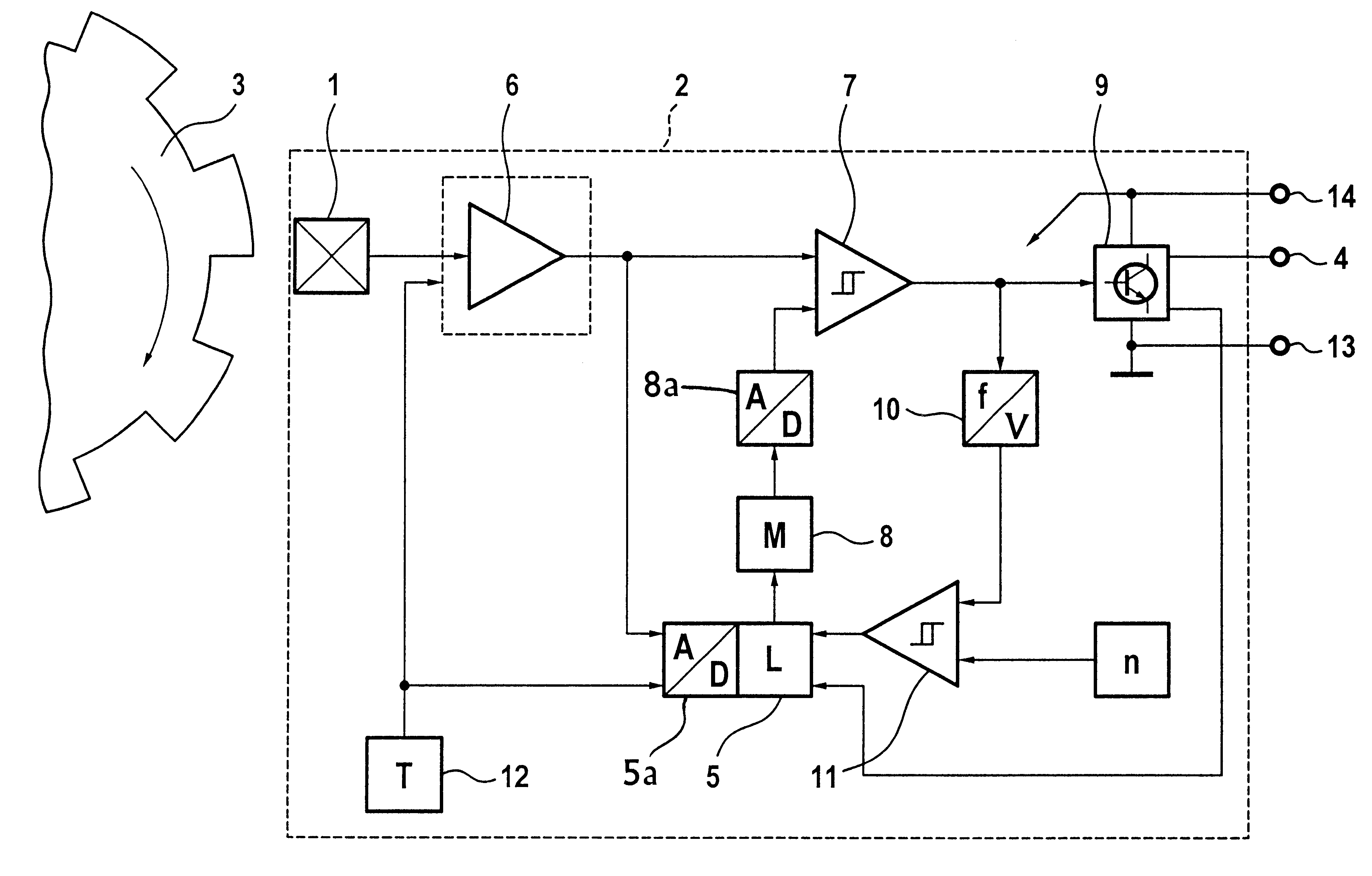
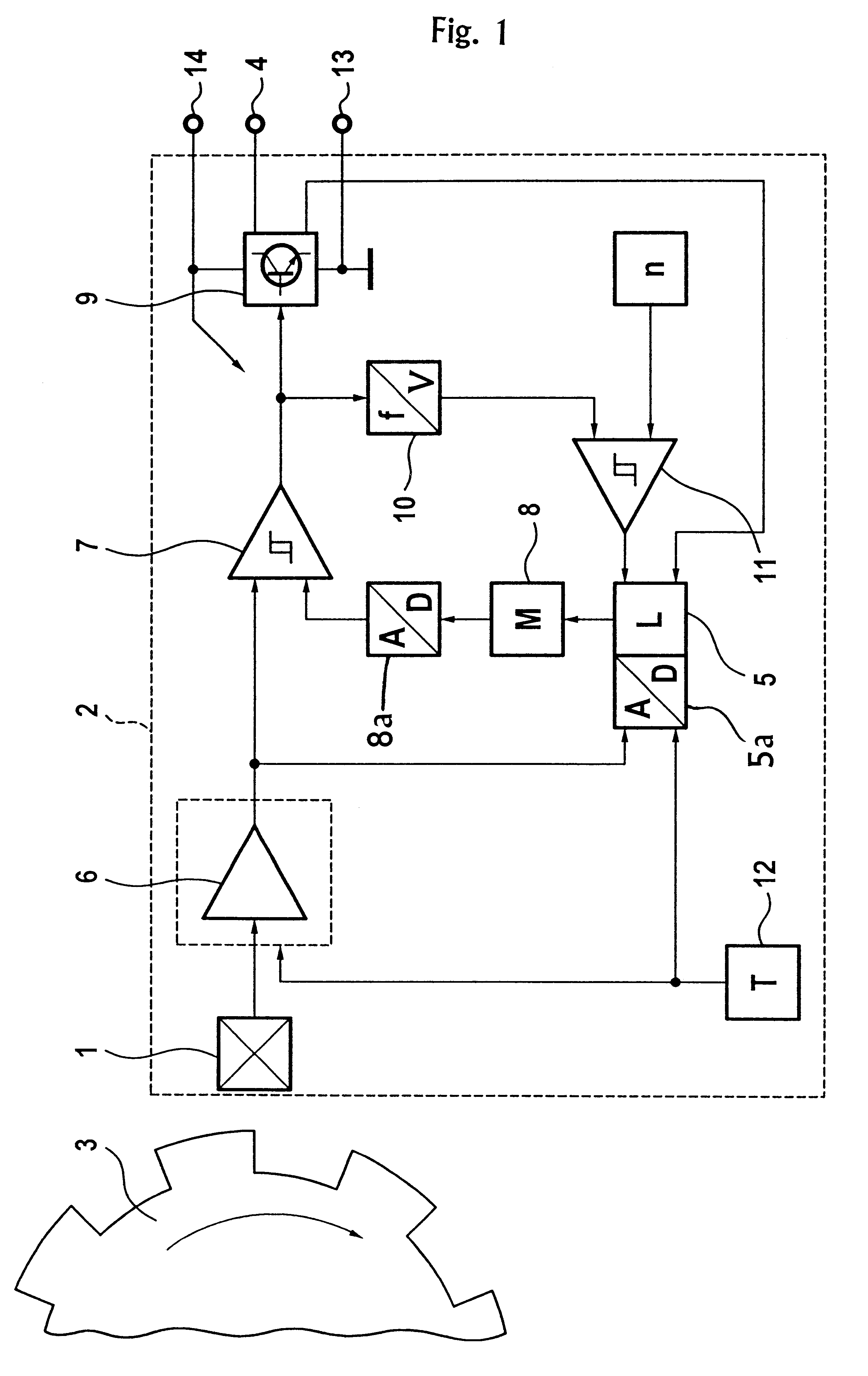
In the drawing, a rotational speed sensor 2 according to the present invention is shown with a detector element 1 arranged adjacent to a pulse wheel 3 made of ferromagnetic material. The sensor 2 records the disturbances, produced by the pulse wheel 3. In a preferred embodiment, the detector element 1 comprises a Hall effect detector with a permanent magnet incorporated therein. The sensor 2 generates a signal in re sponse to a change in the magnetic field in the Hall effect detector 1 and transmits an appropriate binary voltage signal via an output terminal 4.

Alternatively, the detector 1 may comprise a magneto-resistive resistor instead of a Hall effect detector. Furthermore, if the pulse wheel 3 comprises a magnetic pole wheel, the permanent magnet in the Hall effect detector is not required and may be dispensed with.

For control purposes and for automatically setting the switching points, the sensor 2 further comprises a logic circuit 5 with an analog / digital converter 5a. The lo...


PUM


Abstract

A magnetically sensitive sensor for counting pulses for measuring rotational speeds and angular positions of a rotating component via a pulse transmitter connected for rotating with the rotating component automatically adapts its switching points to the respective measurement location conditions. A logic unit initiates automatic adaptation of the switching points from an original state when an operating parameter first exceeds a limit value after the supply voltage of the sensor turned on. The original state is not preset or is coarsely preset. The configuration of the switching points is then stored in a non-volatile data memory specifically for the sensor.

Description

1. Field of the InventionThe present invention relates to a sensor for counting pulses of a rotating pulse transmitter for measuring rotational speeds and angular positions of a rotating component to which the pulse transmitter is connected. More specifically, the present invention relates to a magnetically sensitive sensor for counting pulses of a magnetically acting pulse wheel, the sensor being equipped for automatically adapting its switching points to the respective measurement location conditions.2. Description of the Related ArtIn modern motor vehicles, precise determination of the rotational speeds of crankshafts and. camshafts is required. In addition, to reduce fuel consumption and for the purposes of diagnosis, it is also necessary to be able to ascertain the angular position of the crankshaft and camshaft quickly and precisely. For this purpose, magnetically sensitive sensors are arranged so as to be fixed in the immediate vicinity of a pulse wheel such as a gearwheel, m...

Claims


Application Information

Patent Timeline
IPC IPC(8): G01D5/14G01D5/16G01P3/489G01P3/42G01D5/12F02D41/34
CPCG01D5/145G01P3/489F02D41/009F02D41/0097
Inventor WALLRAFEN, WERNER
Owner CONTINENTAL AUTOMOTIVE GMBH
Why Eureka
Try Eureka