
Synchronous double data rate DRAM

a data rate and synchronous technology, applied in the field of synchronous double data rate dram, can solve the problems of too short available balancing time interval, too short time length, etc., and achieve the effect of ensuring the safety of operation and ensuring the safety of the operation

Inactive Publication Date: 2002-09-03
RENESAS ELECTRONICS CORP
View PDF1 Cites 69 Cited by
  • Summary
  • Abstract
  • Description
  • Claims
  • Application Information

AI Technical Summary

Problems solved by technology

However, the time length may be too short for a safe operation, especially if the read data in the succeeding read operation is opposite to the write data supplied in the write operation.
In this case, the available balancing time interval is too short to assure a safe isolation of the I / O lines from the bit lines.

Method used


Image

  • Synchronous double data rate DRAM
  • Synchronous double data rate DRAM
  • Synchronous double data rate DRAM

Examples


first embodiment

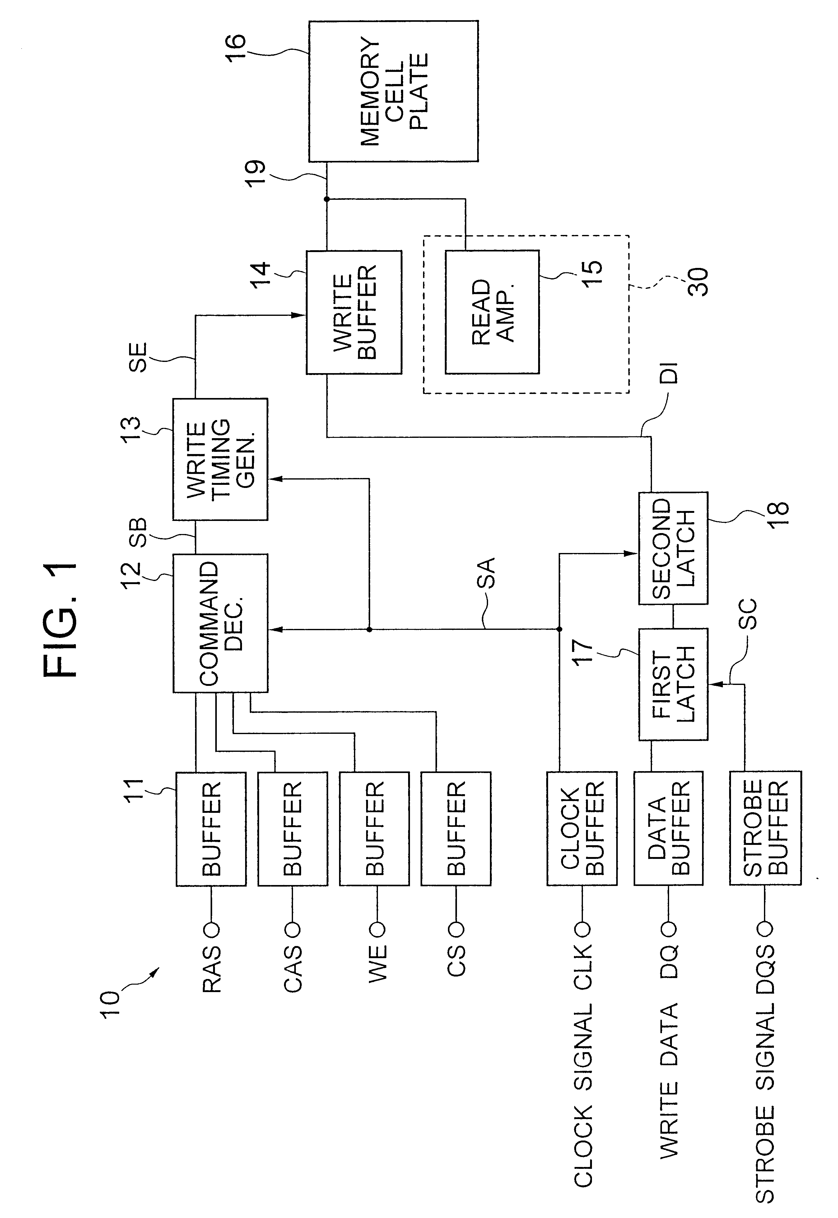
Referring to FIG. 3, a DDR-SDRM according to the present invention includes a memory cell array or memory cell plate 16, a data write section 10, a data read section 30 wherein only a read amplifier 15 is depicted, and an address processing section not shown in the figure.

The data write section 10 includes a plurality of input buffers 11, a command decoder 12, a write timing generator 13, a write buffer (buffer section) 14, and a data latch (latch section) 17. The DDR-SDRM operates for read / write processing with a burst length of two, wherein a read / write operation is conducted for a pair of data at a single read / write cycle to memory cells having successive addresses. The configuration of the address processing section is shown in FIG. 7.

The input buffers 11 in the data write section 10 receive external signals to deliver the same to respective internal sections. The command decoder 12 receives row address strobe (RAS), column address strobe (CAS), write enable signal (WE) and chip...

second embodiment

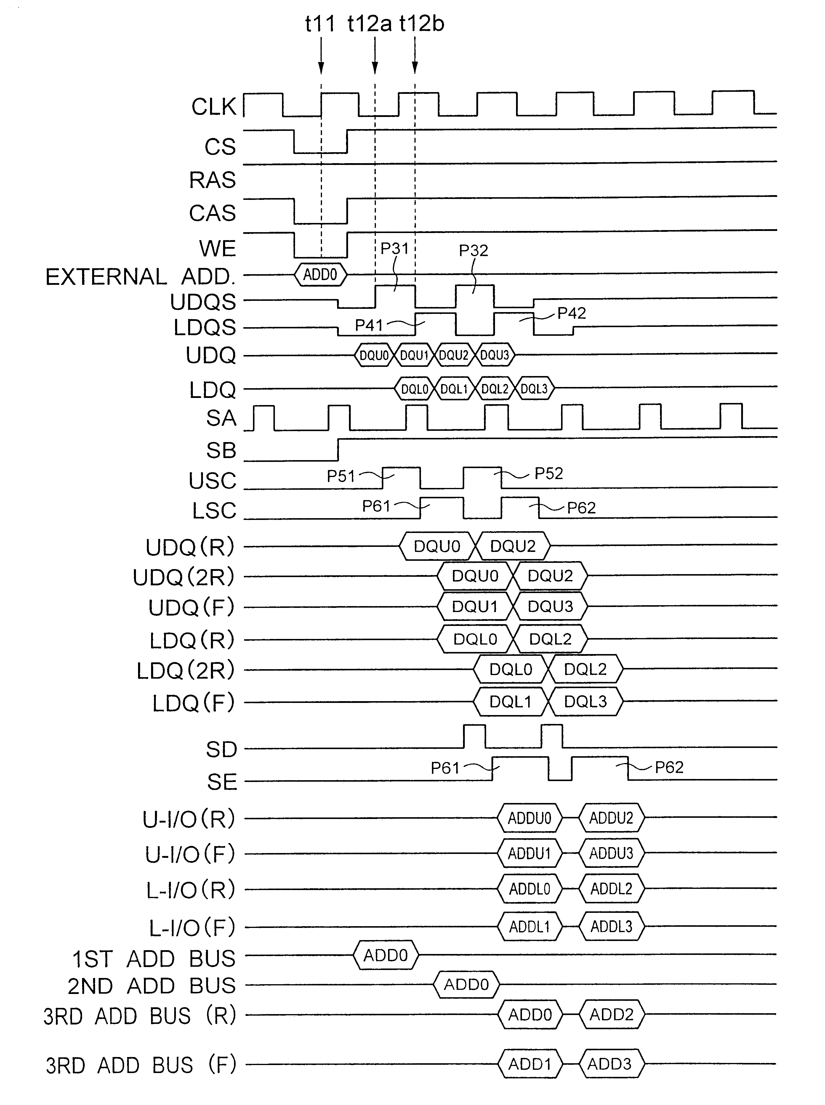
Referring to Fig, 6, there is shown another timing chart of signals in a DDR-SDRM according to the present invention. In the present embodiment, the input write data are supplied through two sets of input sections. The DDR-SDRM has two sets of write buffers 14, two sets of read amplifiers 15, and two sets of data latches for each of data (R) and (F) corresponding to the two sets of input sections for a single memory cell plate 16. Each set includes eight constituent elements, for example, for processing 64 write data during a single write cycle. These two sets of constituent elements are designated by U-side (upper side in the sequential order) and L-side (lower side in the sequential order) constituent elements in the drawing.

It is to be noted that the number of the input terminals for write data is sixteen, wherein the lower serial numbers (0 to 7) of the input terminals corresponds to L-side set and higher serial numbers (8 to 16) of the input terminals corresponds to U-side set....


PUM


Abstract

A DDR-SDRM includes a data write section including a latch section for latching first write data at a rising edge of a data strobe signal and second write data at a falling edge of the data strobe signal, and a write buffer section for writing the first write data and the second write data at a time based on the signals generated from the data strobe signal. A read operation is conducted based on the system clock signal.

Description

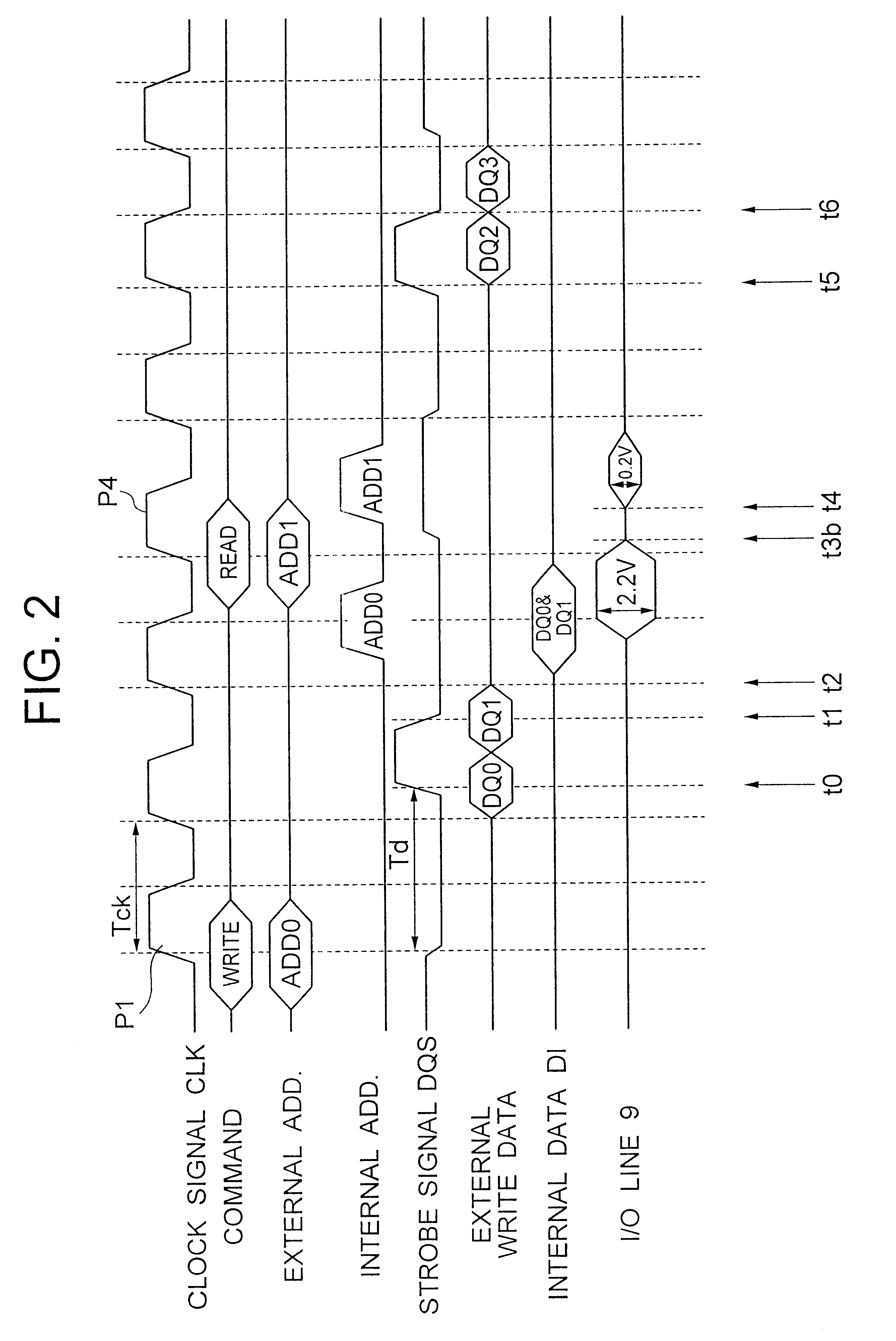
1. Field of the InventionThe present invention relates to a synchronous double data rate DRAM (DDR-SDRM) and, more particularly to an improvement of the read / write performance of a DDR-SDRM.2. Description of the Related ArtIn a DDR-SDRM (which may be referred to as simply SDRAM, hereinafter), the read / write operation is controlled by a system clock signal CLK supplied as an external clock signal, whereas read / write data are transferred between the SDRAM and the external circuit in synchrony with a data strobe signal DQS. The data strobe signal DQS occurs with a specified phase delay with respect to the clock pulse in the system clock signal CLK. The pulses in both the system clock signal CLK and the data strobe signal DQS have the same pulse duration.More specifically, the read / write operation is controlled in synchrony with the system clock signal CLK whereas the latch of the input write data is controlled with the data strobe signal DQS supplied form outside the DRAM. The relation...

Claims


Application Information

Patent Timeline
Patent Type & Authority Patents(United States)
IPC IPC(8): G11C11/4096G11C7/10G11C7/00G11C7/22G11C11/409G11C11/4093G11C11/407G11C11/4076
CPCG11C7/1066G11C7/1072G11C7/1078G11C7/1093G11C7/22G11C11/4076G11C11/4093G11C11/4096G11C11/407
Inventor MURAKAMI, NAOKI
Owner RENESAS ELECTRONICS CORP
Learn More