Method and apparatus for roof ventilation

Inactive Publication Date: 2002-09-10
CAROLINA STOLLENWERK OHAGIN TRUSTEE OF THE CAROLINA STOLLENWERK OHAGIN TRUST +1
View PDF36 Cites 99 Cited by
  • Summary
  • Abstract
  • Description
  • Claims
  • Application Information

AI Technical Summary

Problems solved by technology

In cold climate areas, combinations of high humidity and low outside temperatures can cause frost to form and accumulate on the underside of roof sheathing.
Unfortunately, venting a tile roof presents architects, roofers, and contractors with a serious challenge; how to properly ventilate without leakage, and without destroying the integrity of th

Method used


Image

  • Method and apparatus for roof ventilation
  • Method and apparatus for roof ventilation
  • Method and apparatus for roof ventilation

Examples


Embodiment Construction

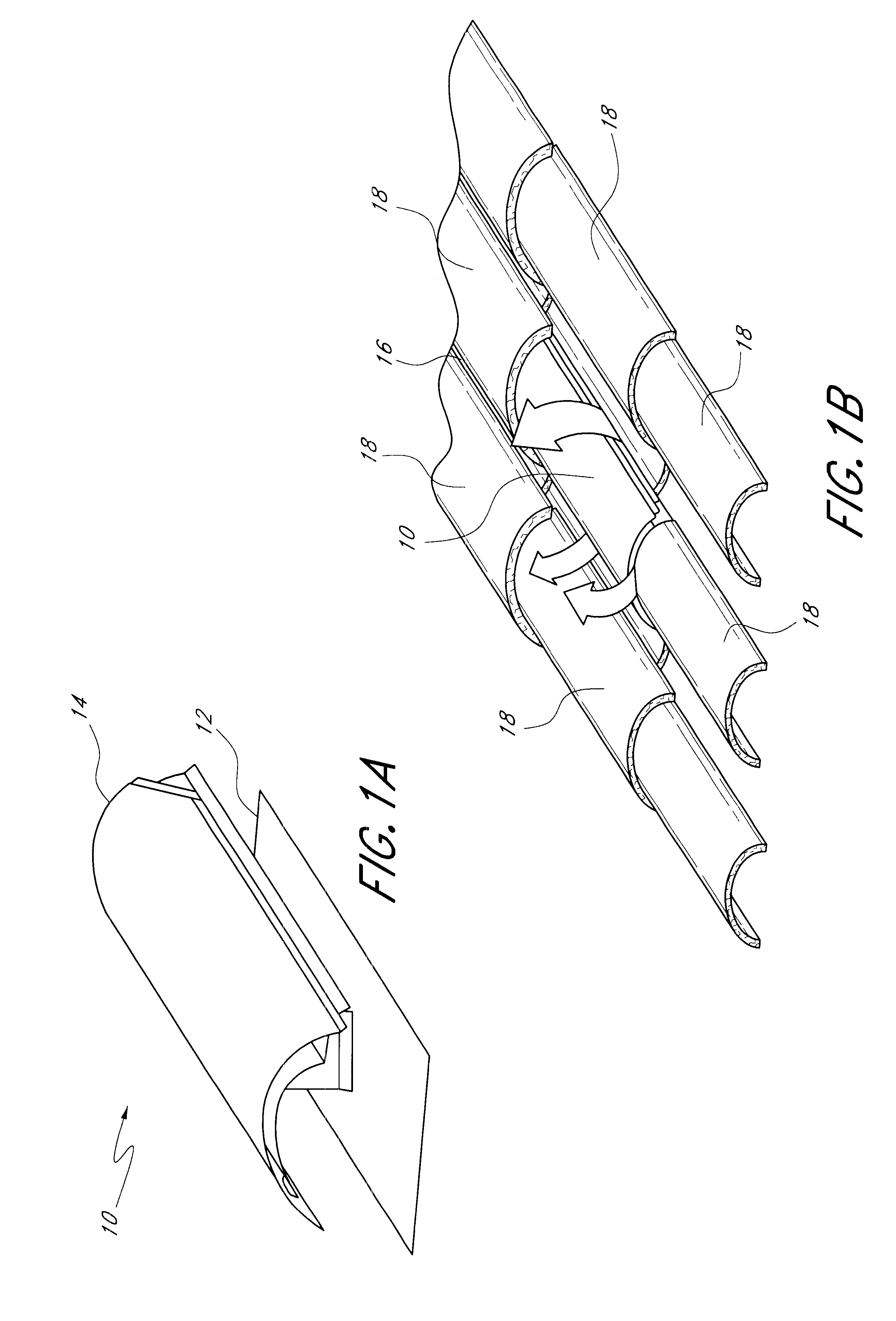
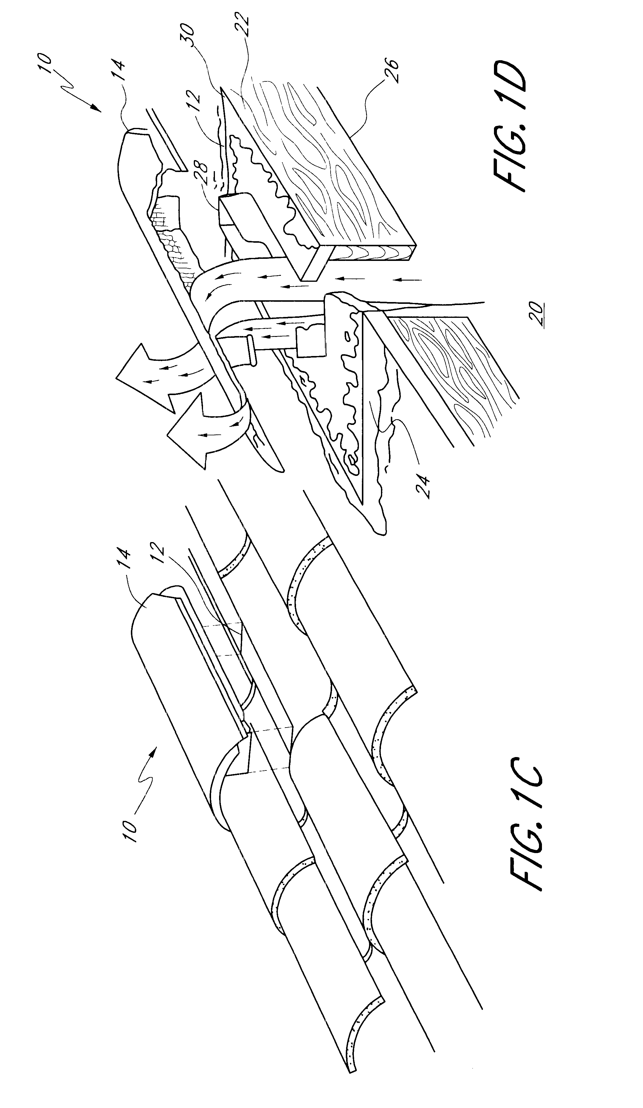
FIGS. 1a-d are a series of perspective views of a mission-style cloaked vent tile 10 of the roof vent apparatus of this invention, where FIG. 1a illustrates an isolated vent base 12 and vent cap 14, FIG. 1b illustrates the vent 10 as installed on a roof 16 in conjunction with and surrounded by standard complementary mission-style tiles 18, and FIG. 1c illustrates the vent cap 14 being inserted over the vent base 12.

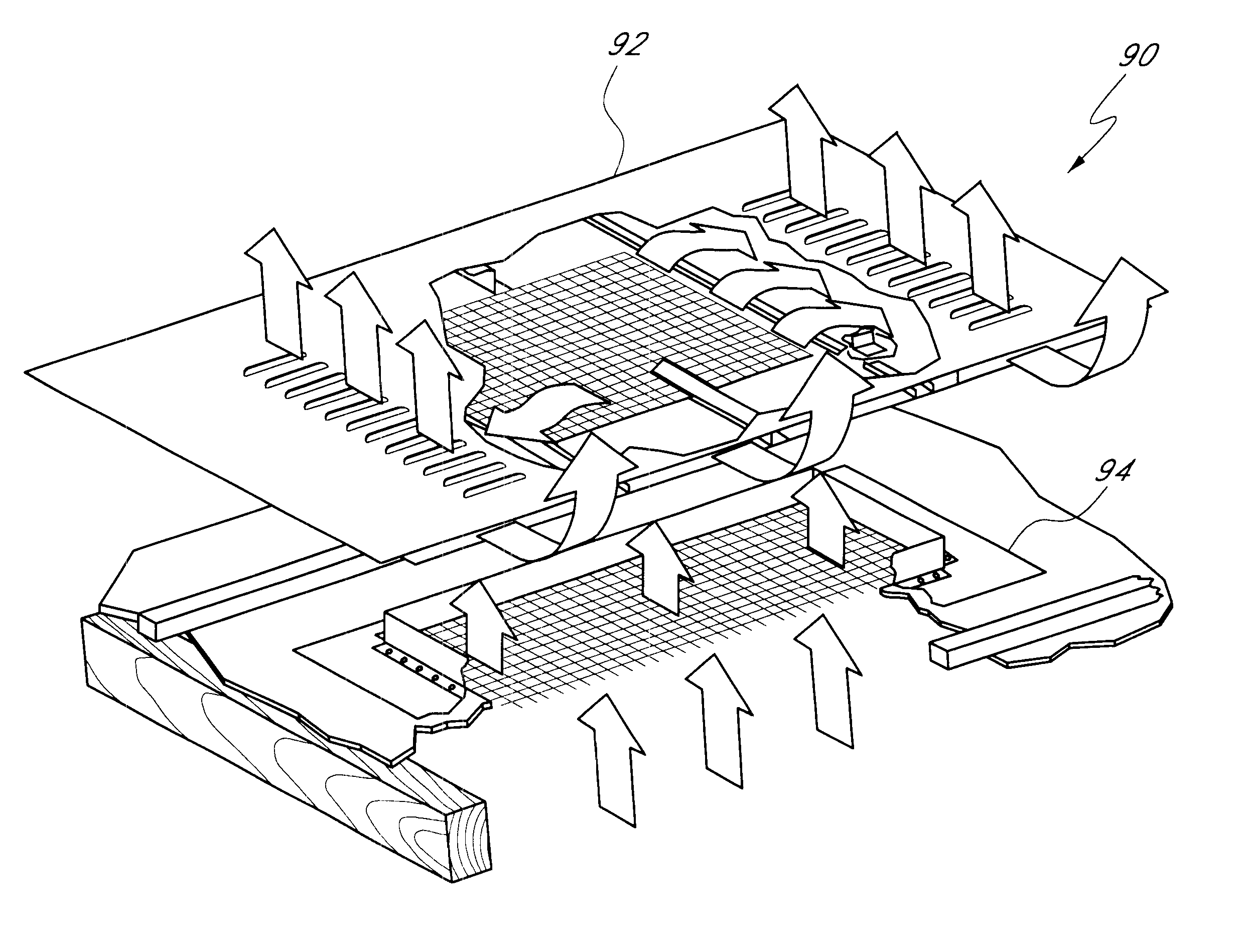
FIG. 1d is an exploded and partially cutaway perspective view illustrating the air flow pattern from the attic volume 20 through the vent 10. This view also serves to illustrate the installation steps:

Vent base 12 is positioned on roof deck 22 and roof underlayment 24 between roof rafters 26. Vent base opening 28 may be used to mark the roof, so that an appropriate-sized hole is cut into the roof. Flange 30 of vent base 12 is installed and sealed to the roof by cement and nails, and additional flashing is placed and sealed around the flange if necessary. The vent cap 14 i...


PUM


Abstract

A roof ventilation apparatus provides a vent tile shaped like a roof tile itself, and thus is inconspicuous and unobtrusive when installed, and blends with the field and/or ridgeline tile. The base of the unit may be used to mark the opening, after which a hole is cut in the roof, roofing cement is applied to the base flange, and the base is secured in place. The unit cover is then placed over the base and the remainder of the roof tile application is completed.

Description

1. Field of the InventionThis invention relates generally to building ventilation, and more specifically to an improved method and apparatus for constructing and installing roof ventilation units for attics and other confined spaces.2. Description of the Prior ArtIt is desirable to ventilate attics and other confined spaces in a building unit to remove accumulated heat and moisture. For example, solar radiation is the principal source of heat in an unventilated attic of a home. Temperatures can reach one hundred fifty degrees Fahrenheit or more when the sun is at its zenith, even when the outside temperature is in the ninety to one hundred degree range. In cold climate areas, combinations of high humidity and low outside temperatures can cause frost to form and accumulate on the underside of roof sheathing.As the threat of indoor air pollution becomes increasingly prevalent, more and more people are concerned about properly ventilating their homes. Unfortunately, venting a tile roof...

Claims


Application Information

Patent Timeline
IPC IPC(8): E04D1/30E04D13/00E04D13/17F24F7/02
CPCE04D1/30E04D13/17F24F7/02E04D2001/302E04D2001/309F24F2007/004
Inventor O'HAGIN, HARRY THEODORE
Owner CAROLINA STOLLENWERK OHAGIN TRUSTEE OF THE CAROLINA STOLLENWERK OHAGIN TRUST
Why Eureka
Try Eureka