Toilet tank fill valve with float

a technology of filling valve and toilet tank, which is applied in the direction of valve actuation float, functional valve type, valve operation means/release devices, etc., can solve the problems of clogging of diaphragm valve, unwieldy design, and suffering of conventional valve assembly, and achieves efficient operation

Inactive Publication Date: 2002-09-17
BRASSCRAFT MFG CO
View PDF15 Cites 27 Cited by
  • Summary
  • Abstract
  • Description
  • Claims
  • Application Information

AI Technical Summary

Benefits of technology

The present invention overcomes the disadvantages of the prior known reservoir fill assemblies by providing an efficient fill valve for filling the tank and incorporating a pilot operated valve for efficient operation.

Problems solved by technology

However, the conventional valve assemblies have suffered from several disadvantages, including noise, clogging of the diaphragm valve due to foreign bodies, unwieldy design due to the presence of a conventional ballcock, and sluggish action of conventional ballcocks.
However, such assemblies do not accommodate the position of the fill valve in different tanks.
However, these adjustment assemblies have been found to be awkward and clumsy, in some instances, requires removal from the tank to adjust the length of the standpipe.

Method used


Image

  • Toilet tank fill valve with float
  • Toilet tank fill valve with float
  • Toilet tank fill valve with float

Examples


Embodiment Construction

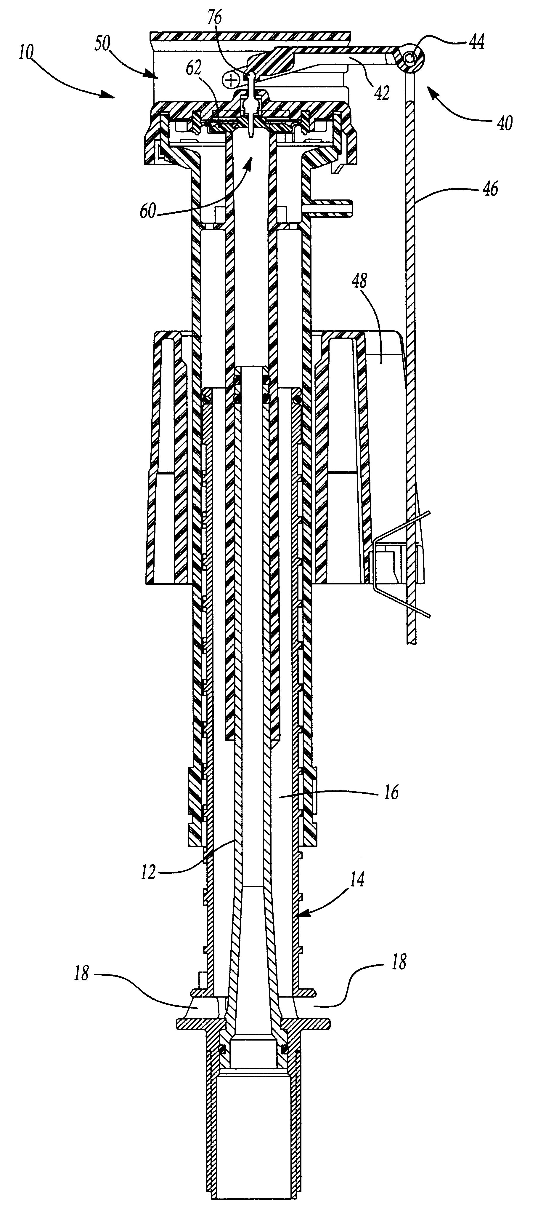
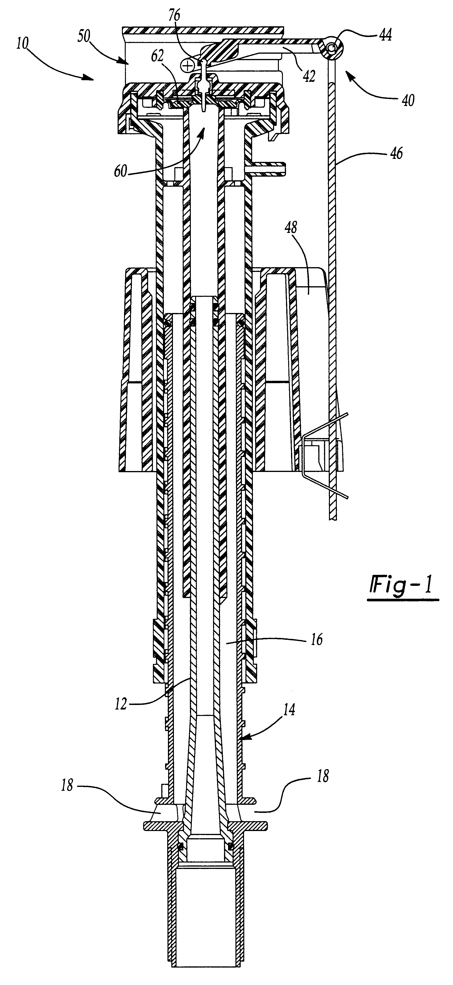
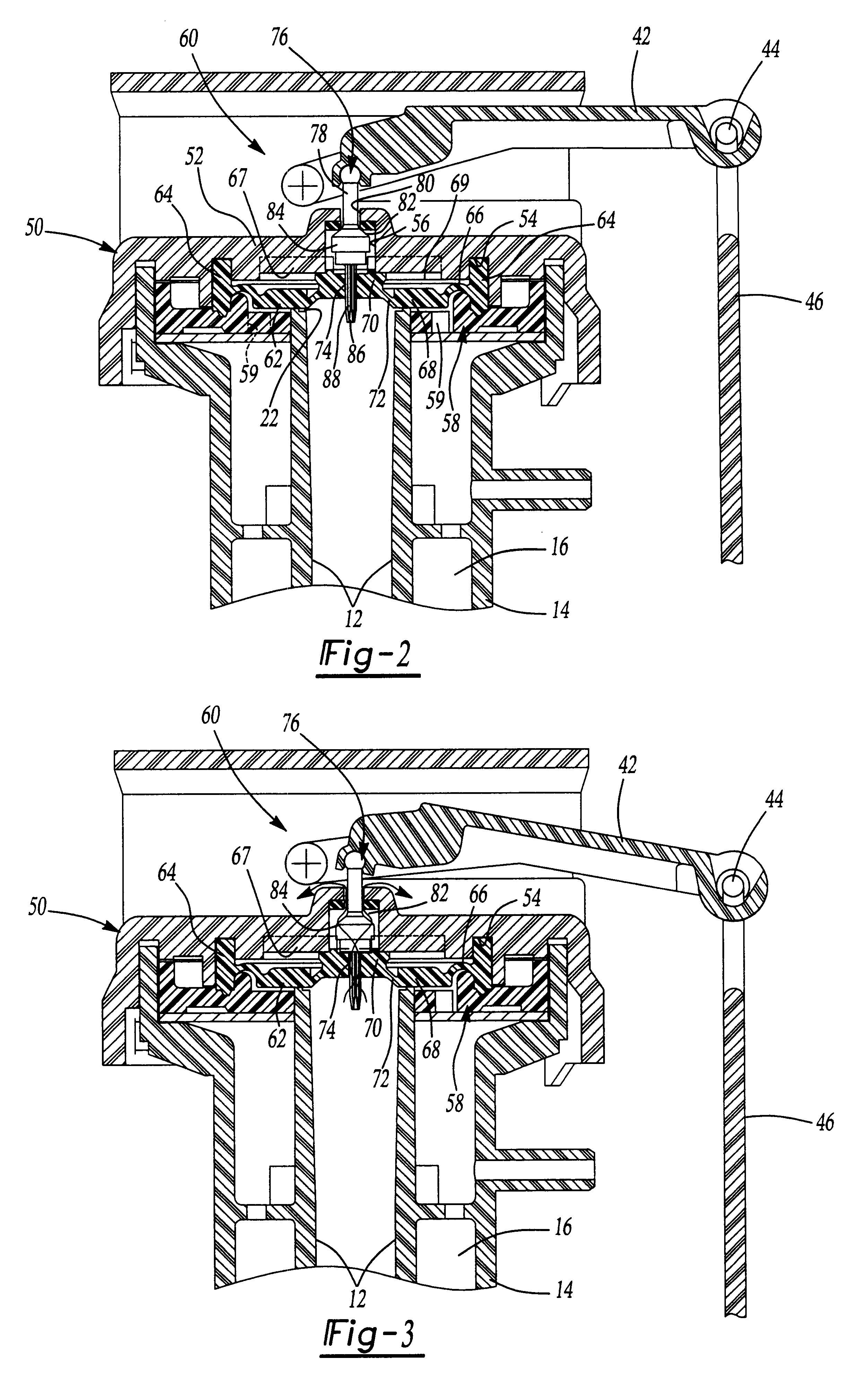
Referring to the drawing, there is shown a float operated valve assembly 10 for controlling the filling of a reservoir such as a toilet tank and to direct fluid for flushing upon actuation. As is well known, upon actuation of a toilet flush lever, the water from the toilet tank is directed to the bowl for removal of waste. The valve assembly 10 controls the filling of the toilet tank to prepare for the next flush.

The float operated valve assembly 10 of the instant invention includes a valve housing 50 connected to and in communication with a height adjustable vertical standpipe 12 and water discharge pipe 14. Water discharge pipe 14 has a larger diameter than standpipe 12 and surrounds and is concentric with standpipe 12. In the embodiment illustrated in the drawings the standpipe 12 and water discharge pipe 14 are of coaxial construction. Discharge pipe 14 has a discharge passage 16 and includes discharge ports 18 through which water can exit the discharge passage 16 and flow into ...


PUM


Abstract

A fill valve assembly for a toilet tank including a vertical standpipe, a pilot valve assembly located at the top end of the standpipe, and a vertically movable float which is connected to the pilot valve assembly. The pilot valve assembly opens the valve assembly when the float moves vertically downward and closes the valve assembly when the float moves vertically upward.

Description

I. Field of the InventionThe instant invention relates to fill valves with floats, and, in particular, to toilet tank fill assembly having a float and a pilot operated fill valve.II. Description of the Prior ArtToilet tank fill valves with ballcocks are well known and in common usage. However, the conventional valve assemblies have suffered from several disadvantages, including noise, clogging of the diaphragm valve due to foreign bodies, unwieldy design due to the presence of a conventional ballcock, and sluggish action of conventional ballcocks. Prior known toilet fill valves may employ a ball float depending from an actuator arm or a float reciprocally mounted to the mounting tube for actuation of the fill valve when the fluid level drops below a predetermined level. As the water level reaches a full position, the buoyancy of the float will cause the fill valve to shut off. It is desirable for the valve to fill the reservoir as quickly as possible by maintaining a near maximum fl...

Claims


Application Information

Patent Timeline
Patent Type & Authority Patents(United States)
IPC IPC(8): E03D1/30E03D1/32F16K21/00F16K31/385F16K31/36F16K21/18
CPCE03D1/32F16K21/18F16K31/385Y10T137/7374Y10T137/7413Y10T137/7433Y10T137/7449Y10T137/7472
Inventor GIL, AMOS
Owner BRASSCRAFT MFG CO
Why Eureka
Try Eureka