Replaceable variable stator vane for gas turbines

a technology of stator vane and gas turbine, which is applied in the direction of machines/engines, manufacturing tools, liquid fuel engines, etc., can solve the problems of rotor removal, inability to remove the rotor, and the inlet guide vanes in the lower inlet casing being removed and replaced, etc., to achieve the effect of reducing the cost of operation, time-consuming and expensive, and improving the service li

Inactive Publication Date: 2002-09-17
GENERAL ELECTRIC CO
View PDF11 Cites 23 Cited by
  • Summary
  • Abstract
  • Description
  • Claims
  • Application Information

AI Technical Summary

Benefits of technology

Thus, in one aspect, the invention relates to a method of replacing an inlet guide vane from a lower inlet casing of a compressor, the lower inlet casing adapted to be secured to an upper inlet casing at a horizontal joint, wherein the inlet guide vane is supported between radially inner and outer walls of the lower inlet casing, and further wherein the inlet guide vane is formed with an integral stem that extends radially through the outer wall and supports a gear

Problems solved by technology

While removal and replacement of the inlet guide vanes in the upper inlet casing can be accomplished relatively easily while the upper inlet casing is removed, removal and replacement of the inlet gui

Method used


Image

  • Replaceable variable stator vane for gas turbines
  • Replaceable variable stator vane for gas turbines
  • Replaceable variable stator vane for gas turbines

Examples


Embodiment Construction

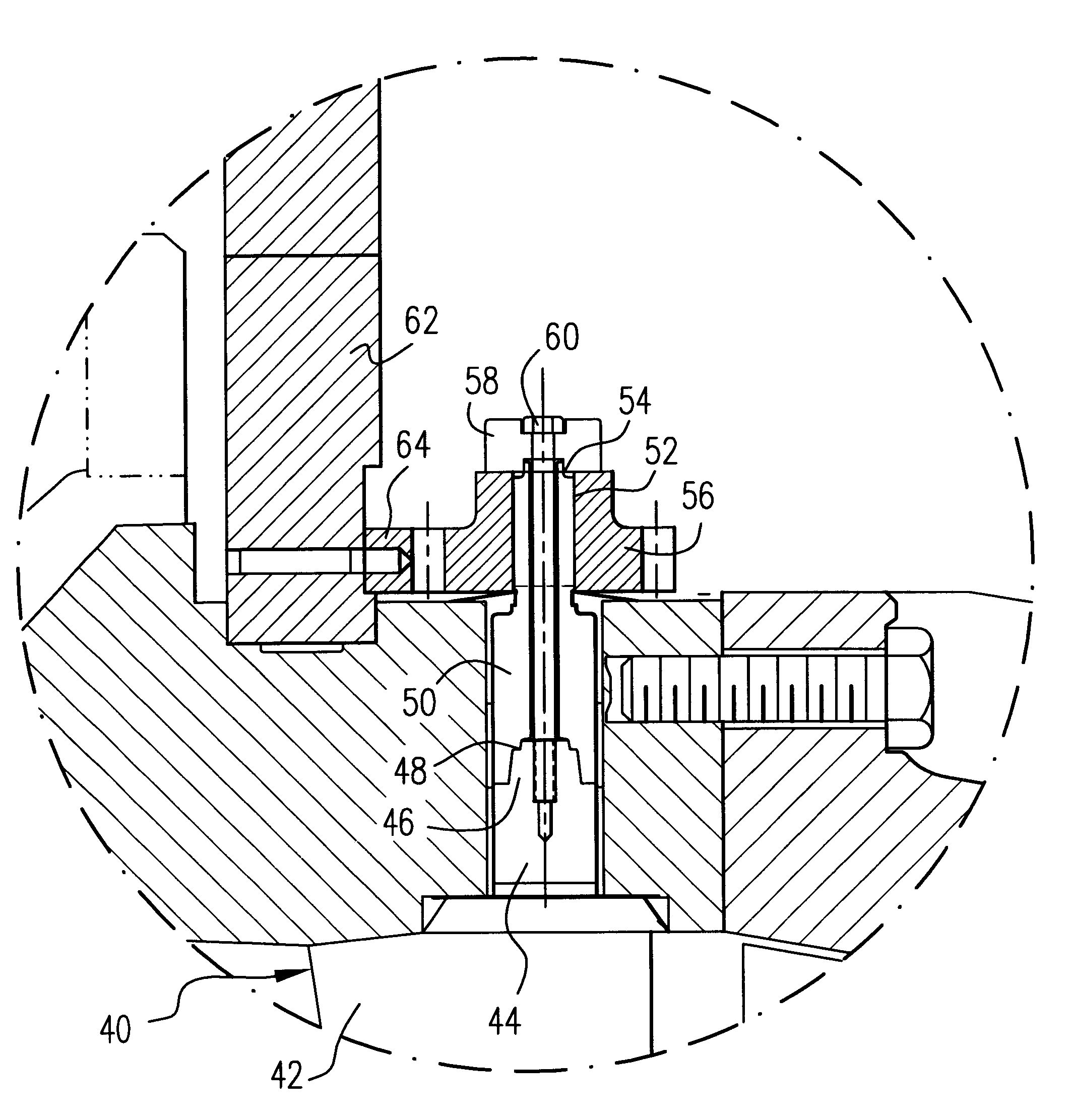
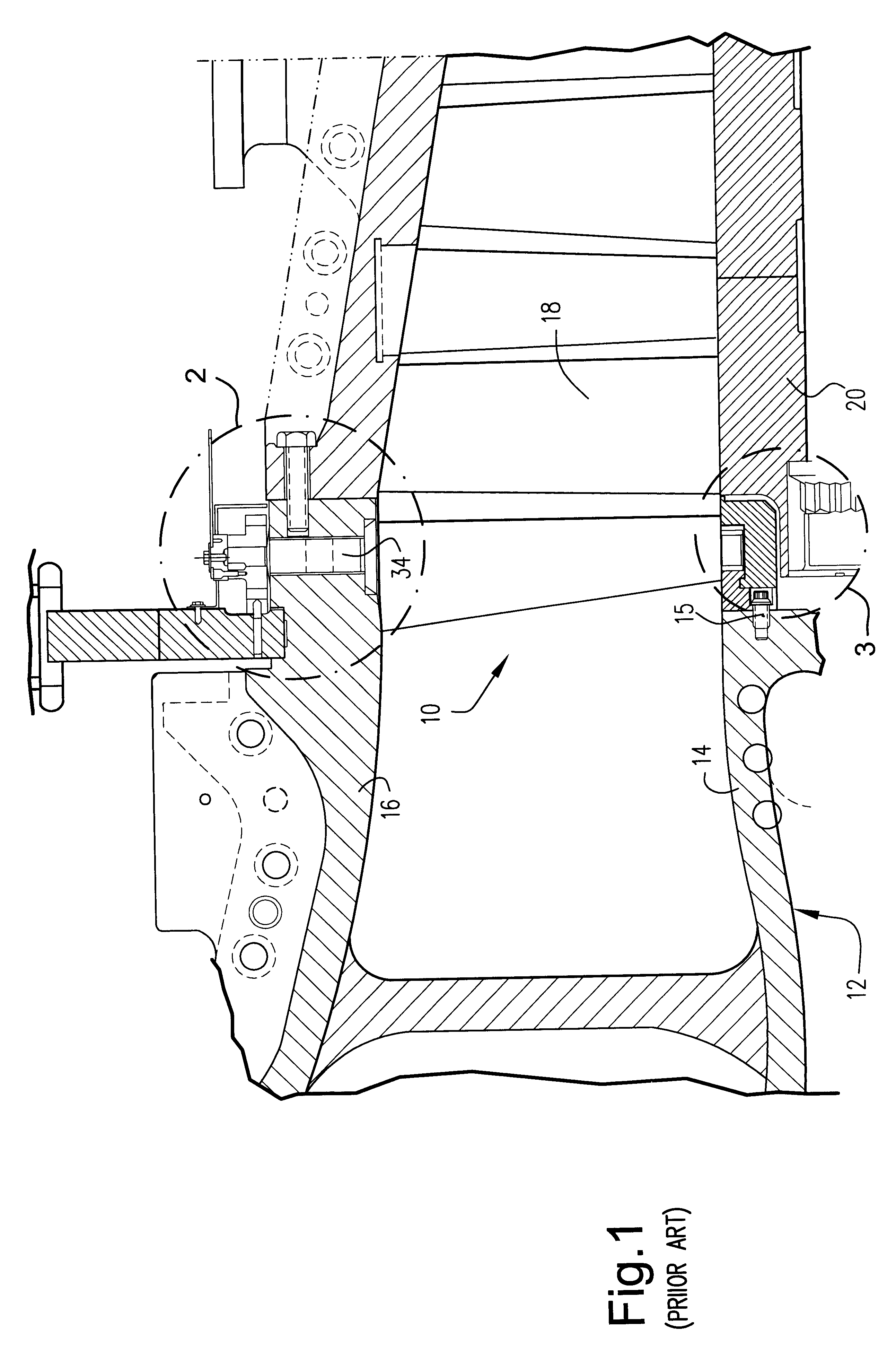
With reference to FIG. 1, an inlet guide vane 10 of known construction is supported within a lower inlet casing 12, between radially inner and outer walls 14, 16, respectively. An annular array of the inlet guide vanes is located forward of the zero or first compressor stage 18, surrounding the rotor 20 (partially shown). It will be appreciated that the inlet casing is split into an upper and lower casings, each extending substantially 180.degree., and each supporting half of the inlet guide vanes. The upper and lower casings are joined together at a horizontal joint. The views shown in all of the Figures are understood to be taken through the lower inlet casing 12, adjacent the horizontal joint.

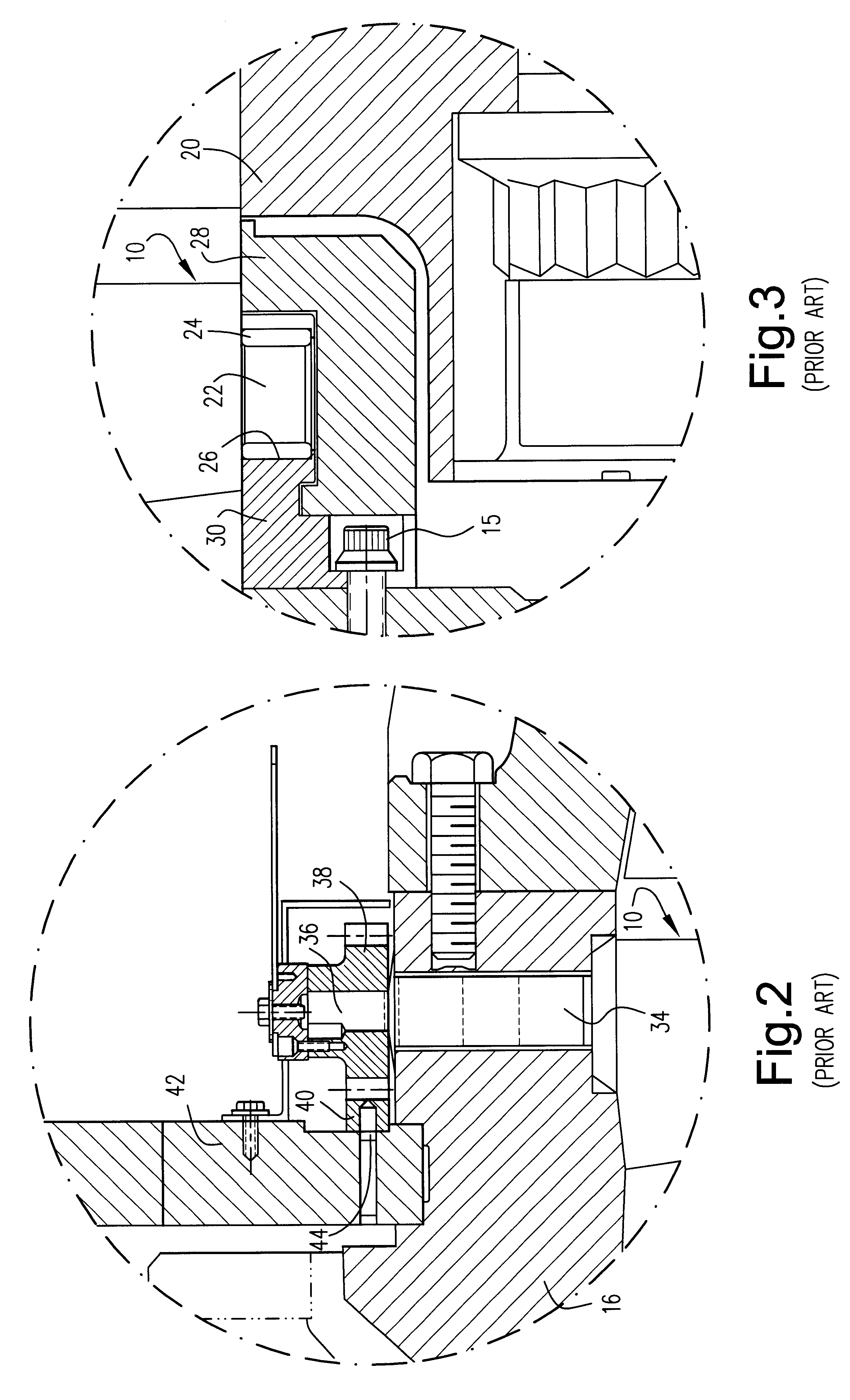
The radially inner end of each of the inlet guide vanes 10 is formed with a cylindrical stem or stub shaft 22 that is supported in a bushing 24 seated within a hole 26 formed in a support segment 30. It will be understood that by supporting the vanes in this manner within the bushings 24 in ...


PUM

PropertyMeasurementUnit
Torqueaaaaaaaaaa

Abstract

A method of replacing an inlet guide vane from a lower inlet casing of a compressor, the lower inlet casing adapted to be secured to an upper inlet casing at a horizontal joint, and after removal of the upper half of the inlet casing but with a rotor of the compressor remaining in place, wherein the inlet guide vane is supported between radially inner and outer walls of the lower inlet casing, and further wherein the inlet guide vane is formed with an integral stem that extends radially through the outer wall and supports a drive gear on its outer end that engages an annular gear rack, the method including a) removing the gear on the radially outer end of the integral stem of the inlet guide vane; b) shearing the inlet guide vane into two cut portions; c) removing the cut portions from inside the lower inlet casing; and d) replacing the inlet guide vane by a modified inlet guide vane having a two-piece stem assembly that enables installation without removal of the rotor. A new inlet guide vane assembly is provided for replacing the vane. The new assembly includes a vane having a cylindrical stub at a radially inner end thereof and a relatively short integral stem at a radially outer end thereof; a jack shaft adapted for connection at a radially inner end thereof to a radially outer end of the integral stem such that torque applied to the jack shaft is transmitted to the vane, a radially outer end of the jack shaft adapted to receive a drive gear. An outer stem piece is seated on the jack shaft and welded to the drive gear to complete a torque transmission path from the drive gear to complete a torque transmission path from the drive gear to the vane.

Description

This invention relates to turbo machinery and, specifically, to a new variable stator vane construction for a turbine compressor and related method for removal of existing variable stator vanes an d replacement with the new vanes, without having to remove the turbine rotor.BACKGROUND OF THE INVENTIONAxial compressors used in gas turbines of the assignee's product line may include as many as eighteen (18) stages, each comprising a bladed disk. In addition, a circumferential array of variable guide vanes are provided at the compressor inlet. The latter serve to adjust the airflow at start-up and provide higher firing temperature at reduced load for regenerative-cycle and combined-cycle applications. These inlet guide vanes are gear actuated from outside the inlet casing, using an annular drive ring, a geared rack, and a drive gear to turn the vanes in unison during operation.Specifically, the inlet guide vanes are supported in two semi-annular halves, referred to herein as the upper a...

Claims


Application Information

Patent Timeline
IPC IPC(8): F01D9/04F01D17/16F01D17/00F04D29/60F04D29/64F04D29/56F04D29/40F01D25/00F01D9/02F02C7/00F02C7/20
CPCF01D9/042F01D17/162F04D29/563F04D29/644Y10T29/49323F05D2260/74F05D2260/4031F05D2230/70F02C7/00
Inventor CRUM, GREGORY ALLANGAGNE, LYNN CHARLESDIXON, WILLIAM EARL
Owner GENERAL ELECTRIC CO
Why Eureka
Try Eureka