

Valve timing control device
a timing control device and valve technology, applied in valve arrangements, machines/engines, mechanical equipment, etc., can solve the problems of difficult to use a straight pin usable in the conventional valve timing control device, the hydraulic pressure exerted on the tier-equipped pin is not adequate, and the beat noise is difficult to preven
- Summary
- Abstract
- Description
- Claims
- Application Information
AI Technical Summary
Benefits of technology
Problems solved by technology
Method used
Image

Examples
embodiment 1
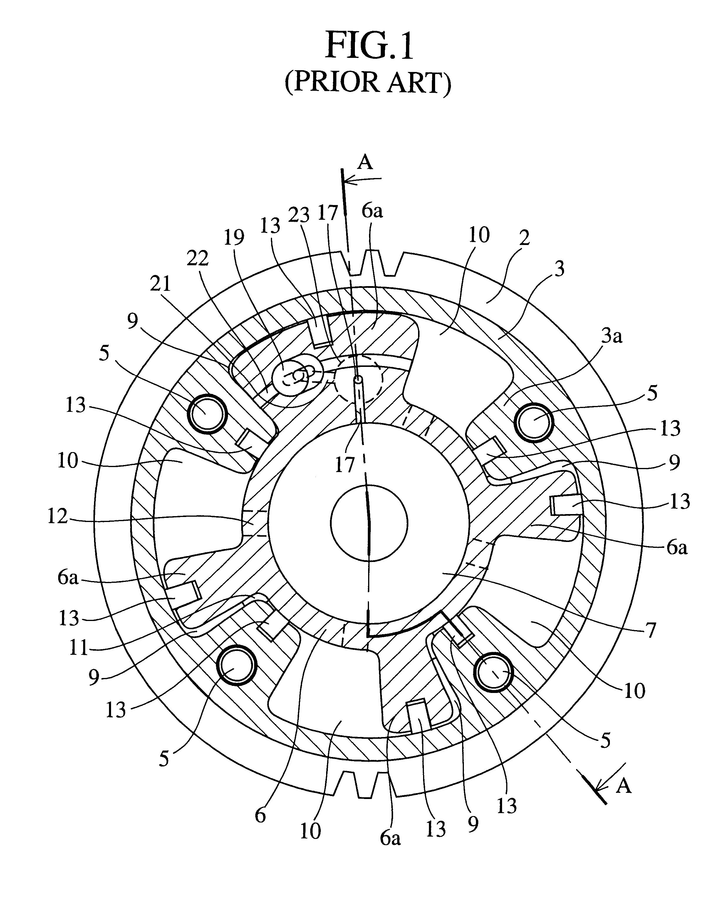
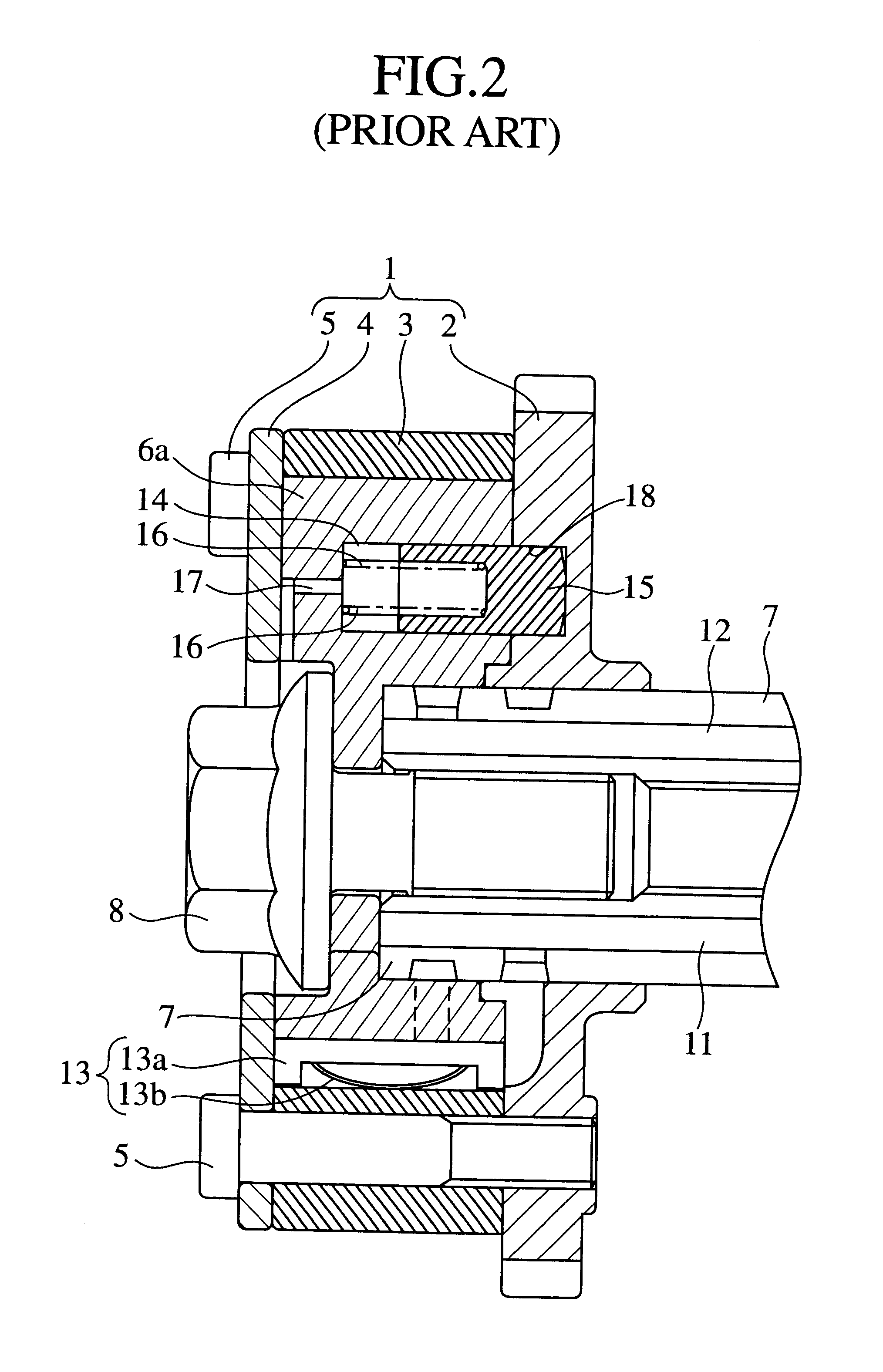
FIG. 6 is a lateral cross sectional view of an internal construction of a valve timing control device as embodiment 1 according to the present invention. FIG. 7 is a longitudinal cross sectional view taken along lines A--A of FIG. 6. FIG. 8 is an enlarged perspective view of a locking / unlocking mechanism of the valve timing control device shown in FIG. 6 and FIG. 7. FIG. 9A and FIG. 9B are longitudinal cross sectional views of an operation of the locking / unlocking mechanism of the valve timing control device shown in FIG. 6 to FIG. 8, FIG. 9A shows a locked state and FIG. 9B shows an unlocked state. FIG. 10 is a graph of a relationship between an operational stroke of a locking member of the locking mechanism of the valve timing control device shown in FIG. 6 to FIG. 9B and a hydraulic pressure exerted on the locking mechanism. Components of the embodiment 1 common to those of the conventional valve timing control device shown in FIG. 1 to FIG. 5 are denoted by the same reference nu...
embodiment 2
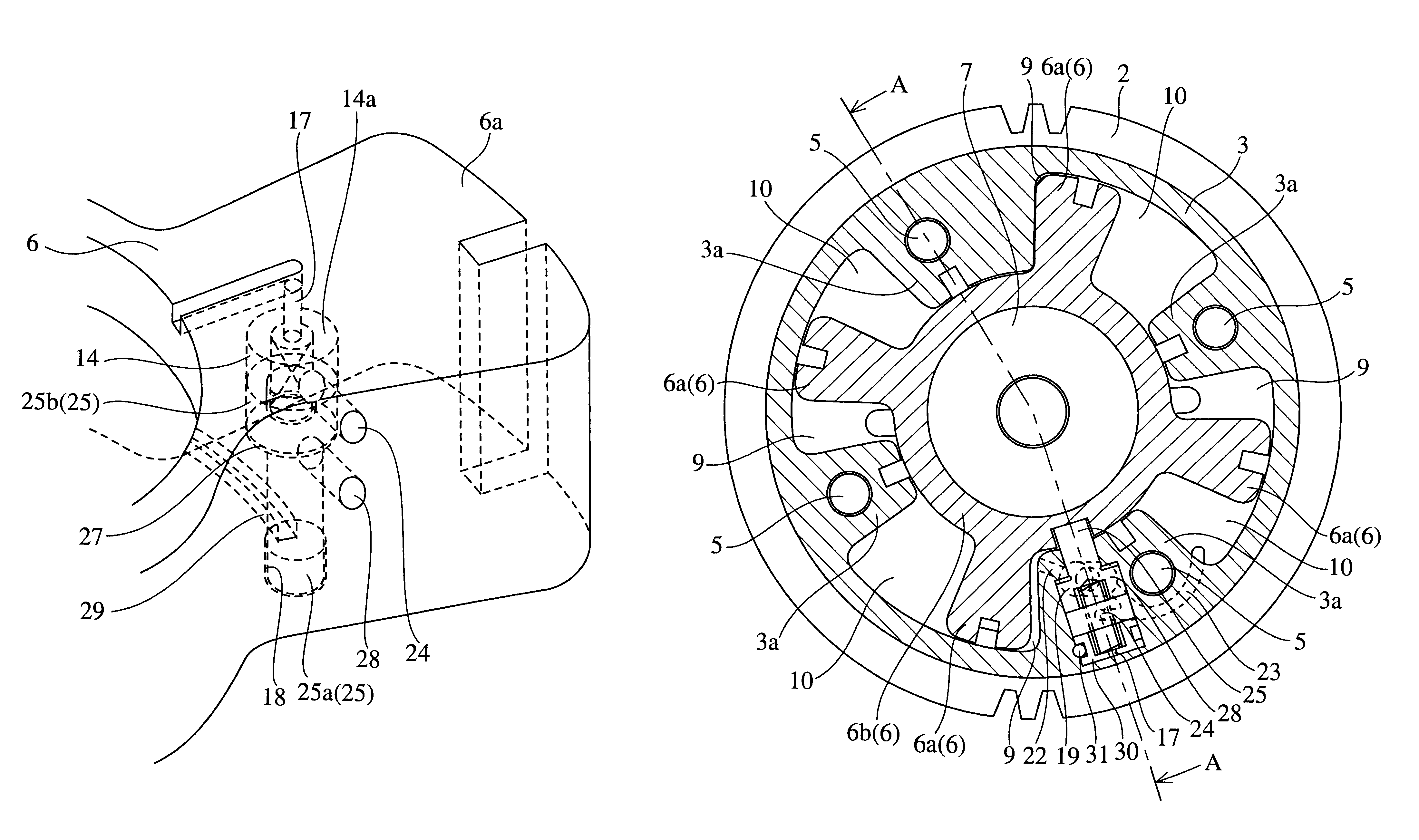
FIG. 11 is a perspective view of an important part of a locking / unlocking mechanism of a valve timing control device as embodiment 2 according to the present invention. FIG. 12A and FIG. 12B are longitudinal cross sectional views of an operation of the locking / unlocking mechanism of the valve timing control device shown in FIG. 11, FIG. 12A shows a locked state and FIG. 12B shows an unlocked state. FIG. 13 is a graph of a relation ship between an operational stroke of a locking member of the lockingmechanism of the valve timing control device illustrated in FIG. 11 to FIG. 12B and a hydraulic pressure exerted on the locking member. Components of the embodiment 2 common to those of the conventional valve timing control device shown in FIG. 1 to FIG. 5 or those of the embodiment 1 are denoted by the same reference numerals and further description will be omitted.
The embodiment 2 is characterized in that a locking pin 25 defined as the tier-equipped pin is used, whereas the straight-sh...
embodiment 3
FIG. 14 is a lateral cross sectional view of an internal construction of a valve timing control device as embodiment 3 according to the present invention. FIG. 15 is a perspective view of an important part of a locking / unlocking mechanism of the valve timing control device shown in FIG. 14. FIG. 16A and FIG. 16B are longitudinal cross sectional views of an operation of the locking / unlocking mechanism of the valve timing control device shown in FIG. 14 and FIG. 15, FIG. 16A shows a locked state and FIG. 16B shows an unlocked state. Components of the embodiment 3 common to those of the conventional valve timing control device shown in FIG. 1 to FIG. 5 or those of the embodiment 1 are denoted by the same reference numerals and further description will be omitted.
With the embodiment 3, a third unlocking hydraulic pressure supply path 28 is disposed at the vane 6a of the rotor 6 and a fourth unlocking hydraulic pressure supply paths 29 is disposed at the sprocket 2, instead of the check ...
PUM
 Abstract
Description
Claims
Application Information