Electric motor drive mechanism for shed forming components of a loom

a technology of electric motor and forming components, which is applied in the direction of weaving, textiles and papermaking, looms, etc., can solve the problems of inability to retrofit existing looms, the need for special shed forming components of looms, and the inability to use conventional heald shafts, etc., to achieve the effect of avoiding repair and maintenance work, reducing costs and materials, and reducing maintenance and repair tim

Inactive Publication Date: 2002-10-08
LINDAUER DORNIER GMBH
View PDF15 Cites 13 Cited by
  • Summary
  • Abstract
  • Description
  • Claims
  • Application Information

AI Technical Summary

Benefits of technology

to provide a heald shaft drive capable of cooperating with conventional rapid action couplings or so-called snap locks between the drive and the heald shafts so that conventional bottom heald shaft motions and detour levers between the shafts and the shaft drives are avoided;
An important advantage of the heald shaft drive according to the invention is seen in that it permits any desired motion profiles for the heald shafts with regard to the loom shed opening profile and any desired shed closure as well as any desired shaft strokes. The shed closure can be coordinated to color and / or other parameters of the weft threads as well as the type of weave. The avoidance of bottom or lower heald shaft motions results in a shaft drive that reduces costs as well as materials. Moreover, maintenance and repair time savings are achieved, for example when shaft exchanges must be made. Repair and maintenance work is avoided particularly of bearings that are conventionally integrated into detour levers, since such detour levers are avoided according to the invention. A very important further advantage is seen in that all conventional looms can be retrofitted with the shaft drive according to the invention, because conventional loom heald shafts with conventional shaft couplings can be connected directly to the present drives.

Problems solved by technology

A disadvantage of that structure is seen in that the loom must be equipped with special shed forming components.
As a result, conventional heald shafts cannot be used and the drive disclosed in the German Patent Publication DE 196 51 799 cannot be used for retrofitting existing looms without substantial changes in the heald shafts, or rather in the coupling portion of the heald shafts.
The drive mechanism between the motion transmission member of the linear D.C. motor and the respective shed forming component also requires a special heald shaft or at least suitable modifications for the heald shaft for the interconnection so that the required heald shafts do not correspond to conventional heald shafts and retrofitting is not possible without substantial effort and expense.
The foregoing conventional technical solutions of the problem how to drive heald shafts in a loom have the disadvantage that it is necessary to lift the shaft packet with the armature of the linear D.C. motor out of the loom when it becomes necessary to exchange the heald shaft, for example when the fabric type is to be changed or when shaft repairs are necessary.
The reinsertion of the shaft packet into the loom may damage the shaft drives.
Another disadvantage is seen in that it is very easy to damage a shaft when the drive motor has a defect since the respective shaft can jam in its guides.
Moreover, such conventional drives are suitable only for relatively narrow looms because a center drive having the same drive conception as a drive that is integrated into the shaft side supports or frame side members is not possible.
Another disadvantage of the drive disclosed in Japanese Patent Publication JP 10-310949 A is seen in that either the heald shafts must have different lengths or shafts having the same length relative to one another must be laterally displaced relative to each other in the weaving loom.
Such a shaft arrangement does not permit efficiently carrying out the preparations for weaving.
Besides, these conventional drives result in relatively wide looms while achieving a comparatively narrow weaving width.
This conventional construction has the disadvantage that the position of the shaft connections from shaft to shaft is different.
Thus, it is no longer possible to exchange one individual shaft for another which can be a substantial disadvantage, particularly in maintaining a large stock of spare parts.
Here again it is more difficult to carry out the preparations for weaving and the coordination of the heald shafts during a shaft exchange is also difficult.
Besides, a super structure is known to provide a certain complexity on the weaving floor.
The insertion of the heald shafts into the loom as well as their removal from the loom is not without its own problems as compared to other conventional heald shafts.

Method used


Image

  • Electric motor drive mechanism for shed forming components of a loom
  • Electric motor drive mechanism for shed forming components of a loom
  • Electric motor drive mechanism for shed forming components of a loom

Examples


Embodiment Construction

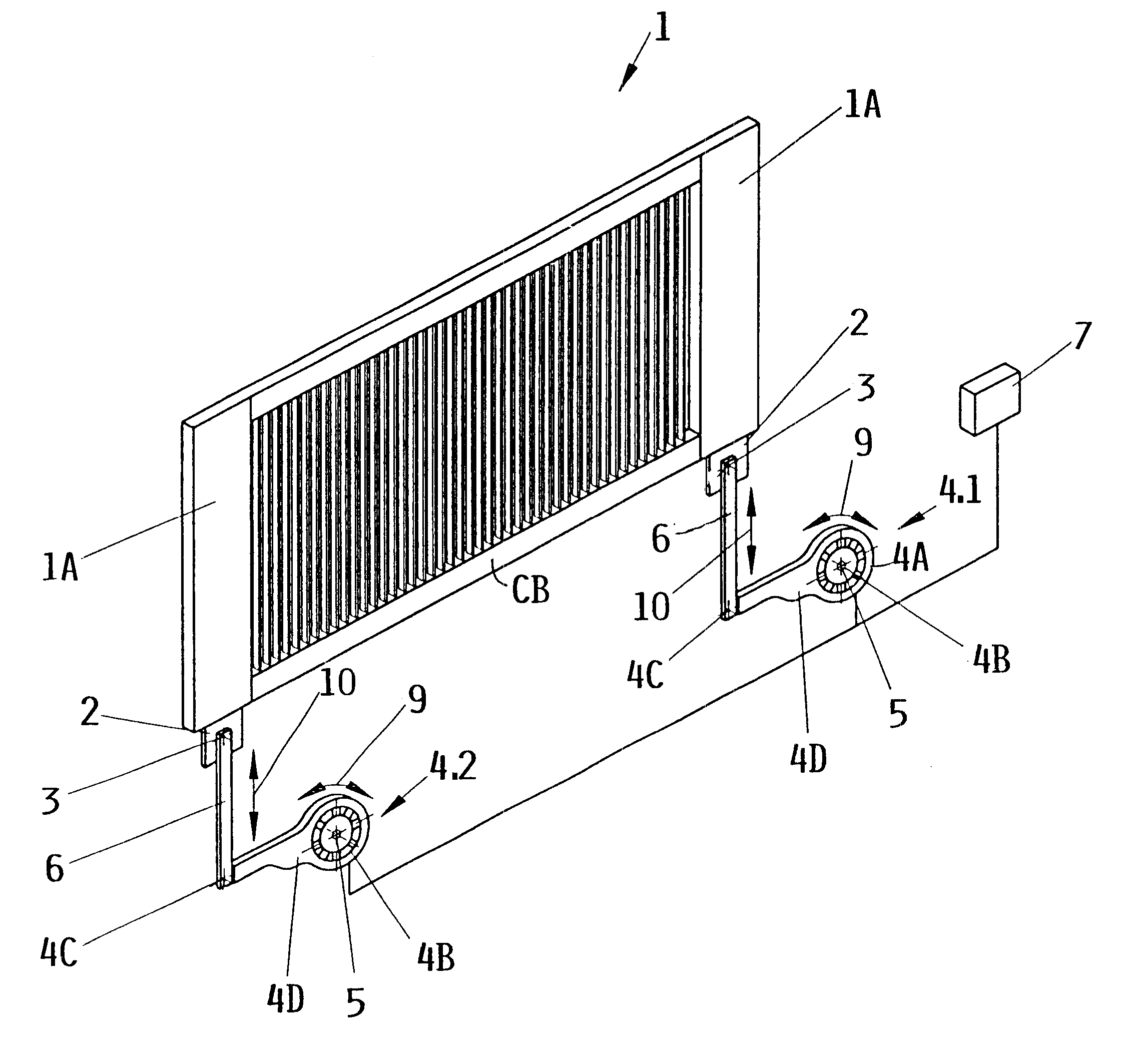
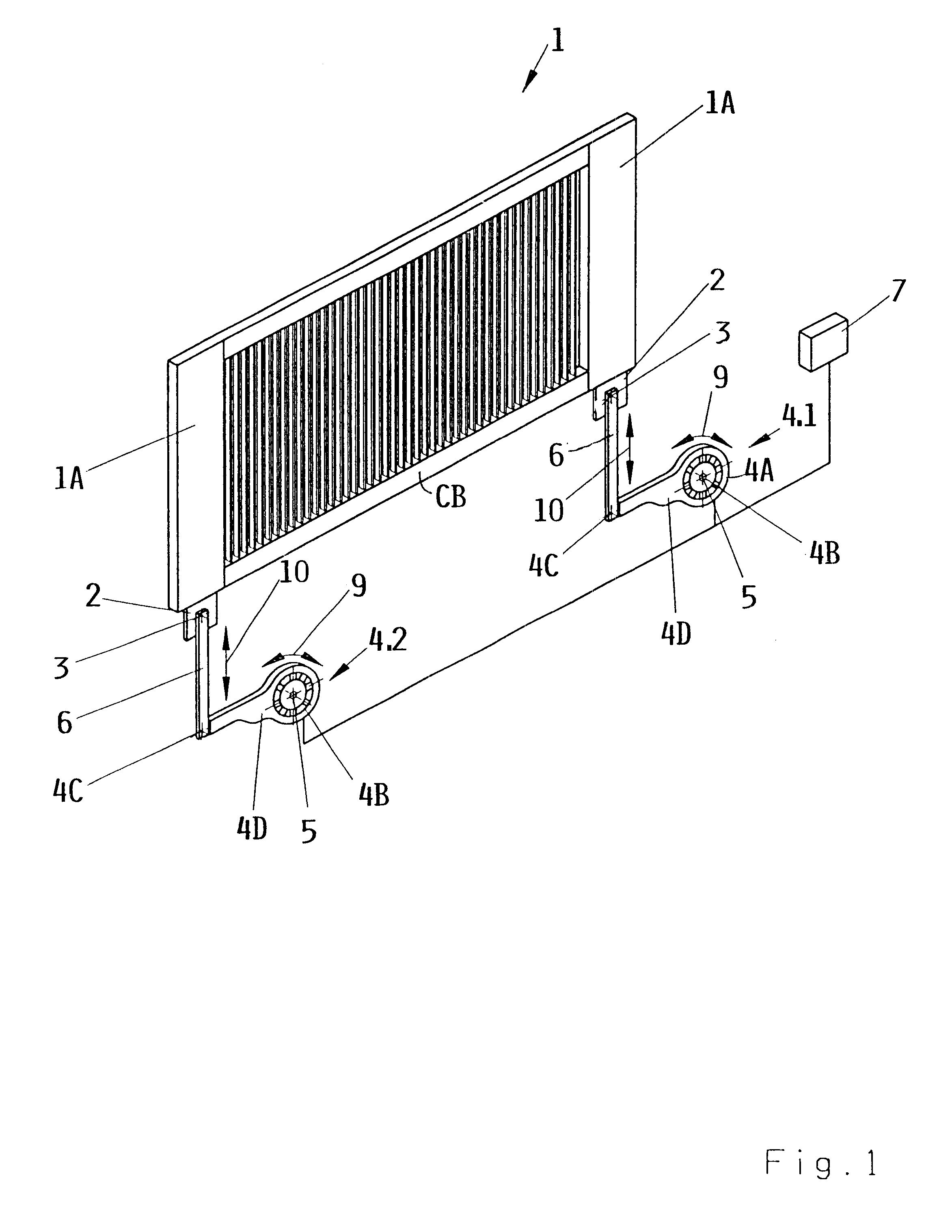
FIG. 1 shows a heald frame 1 having lateral frame sections 1A provided with coupling projections 2. The coupling projections or extensions 2 may be integral parts of the lateral frame sections 1A. The coupling projections 2 form part of a first articulated coupling 3 operatively connecting an upper end of a push-pull rod 6 to the heald frame 1. A second articulated coupling 4C, 11C connects a lower end of the push-pull rod 6 to a drive lever or arm to be described in more detail below. The first and second couplings 3, 4C, 11C or at least the second couplings are preferably so-called quick or rapid action couplings or snap locks which as such are known, for example from German Patent Publication DE 195 48 848 B1.

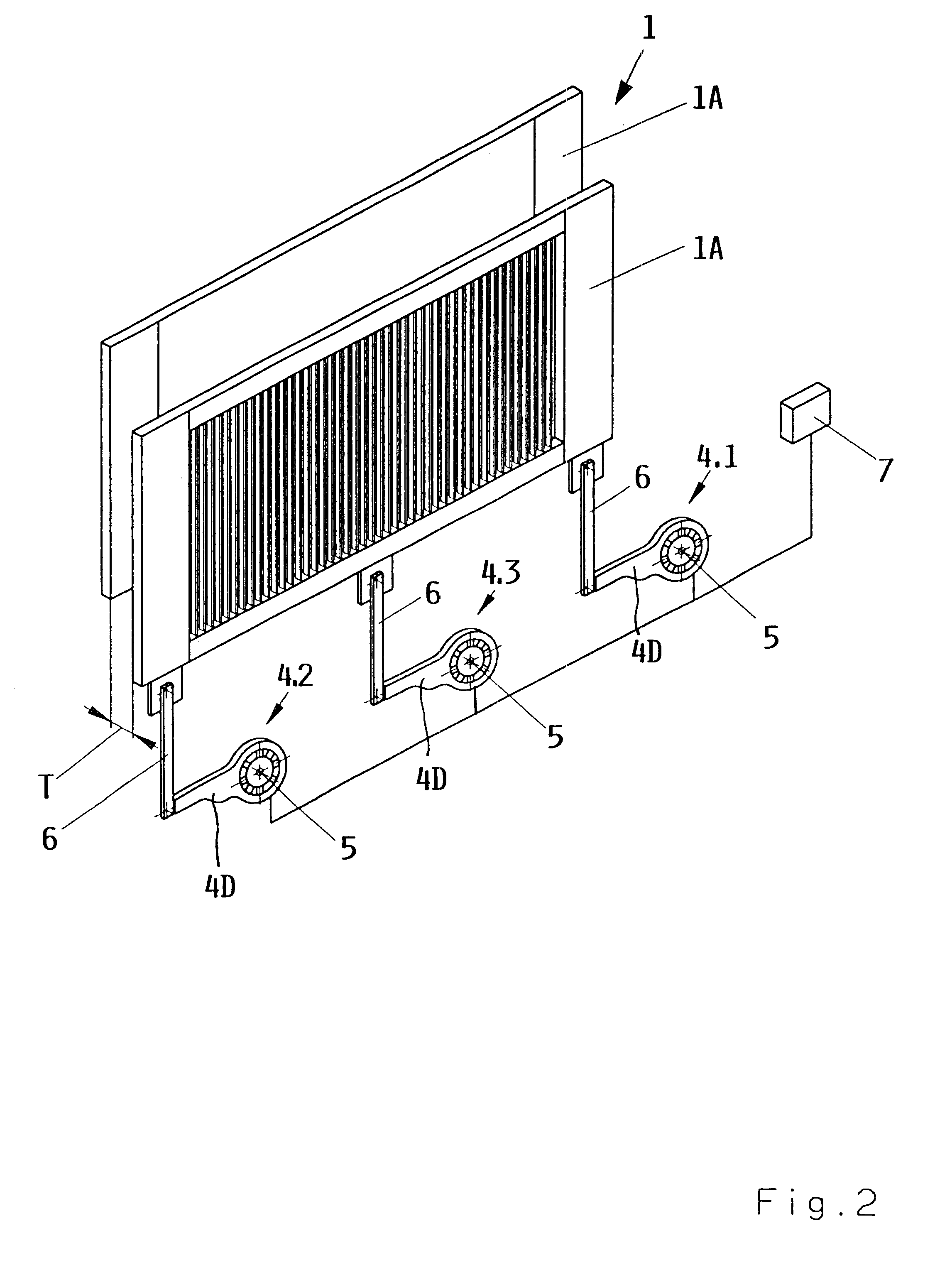
Although FIG. 1 shows two symmetrically arranged drives 4.1 and 4.2, it is possible to provide but one centrally arranged drive 4.3 which would be centrally coupled to a horizontal crossbeam CB of the heald frame 1. Such a central connection of a single drive 4.3 is particul...


PUM


Abstract

The heald shafts of a power loom are driven by electric D.C. or A.C. motors which have an external rotor or an armature connected to the respective heald shaft through two articulated couplings, for example snap locks, and a push-pull rod. The motors receive control signals from a computerized controller for reversing the motion direction of the external rotor or armature. The stators of the motors are rigidly mounted on a fixed axis secured to the loom frame.

Description

PRIORITY CLAIMThis application is based on and claims the priority under 35 U.S.C. .sctn.119 of German Patent Application No. 101 11 017.0, filed on Mar. 7, 2001 in Federal Republic of Germany, the entire disclosure of which is incorporated herein by reference.A power loom has shed forming components such as the heald frames or heald shafts which are operated by electric motors for opening and closing the loom shed in a controlled sequence.BACKGROUND INFORMATIONDrive mechanisms for operating the heald shafts of weaving looms which are not so-called shaft looms or so-called eccentric drive looms are known. These known drive mechanisms can be categorized primarily into two categories. One category includes rotational D.C. motor drives. Another category includes so-called linear D.C. motor drives. The first category of the rotational D.C. motor drives includes motors which are operated to repeatedly reverse their rotational direction, for example in an oscillating manner in order to tr...

Claims


Application Information

Patent Timeline
Patent Type & Authority Patents(United States)
IPC IPC(8): D03C5/00D03C13/00D03C1/14D03D51/02
CPCD03C5/00D03C13/00D03C13/025D03J1/008
Inventor KRUMM, VALENTIN
Owner LINDAUER DORNIER GMBH
Why Eureka
Try Eureka