
Welded heat exchanger with grommet construction

a technology of heat exchangers and grommets, which is applied in the direction of indirect heat exchangers, lighting and heating apparatus, and stationary conduit assemblies, etc., can solve the problems of increasing the length of tubes, increasing the mechanical stress on the tanks and the associated headers, and increasing the stress on the tube-to-header joints

Inactive Publication Date: 2002-10-08
VISTA PRO AUTOMOTIVE
View PDF8 Cites 40 Cited by
  • Summary
  • Abstract
  • Description
  • Claims
  • Application Information

AI Technical Summary

Benefits of technology

It is a further object of the present invention to provide an improved method of assembly of a heat exchanger in which the core assembly can be separately tested and corrections can be made to the tube-to-header joints, if necessary, before the tanks are attached.
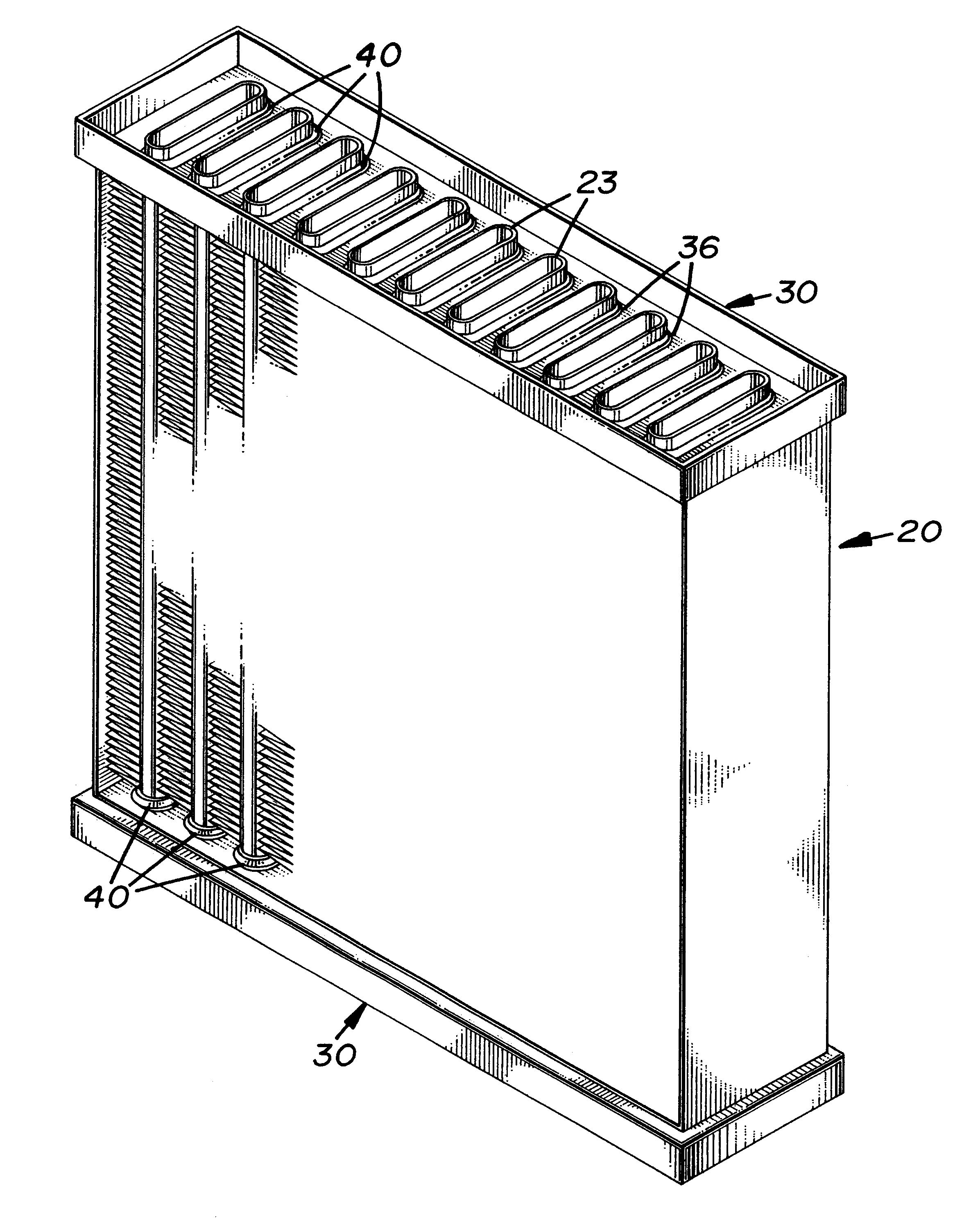
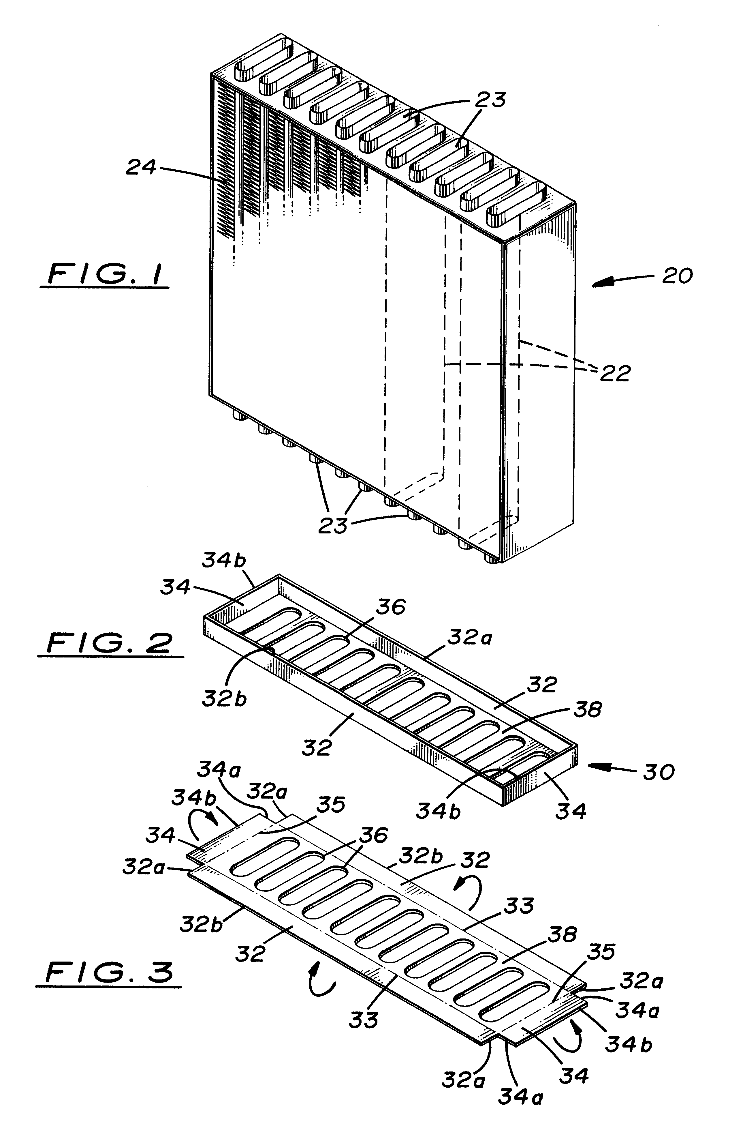
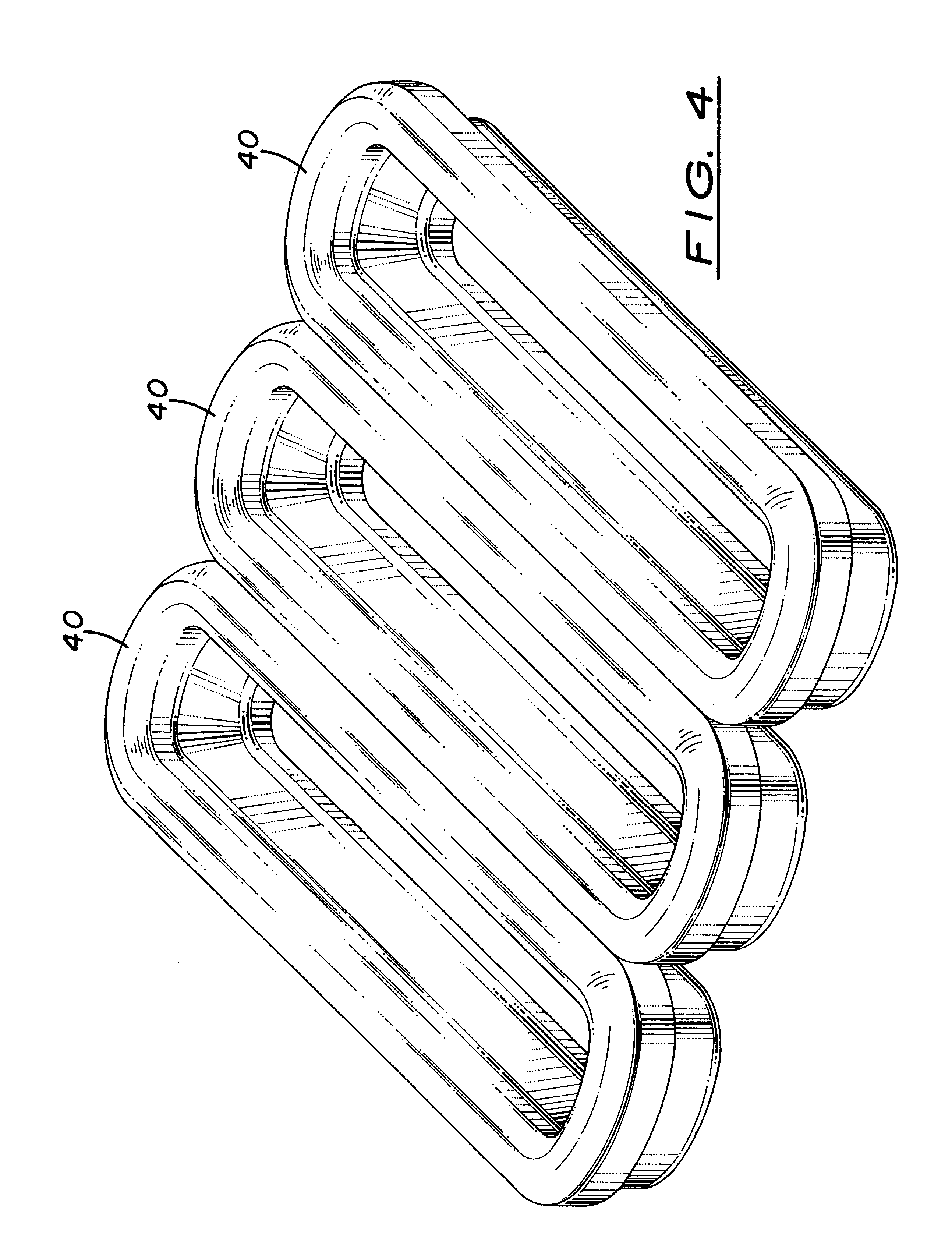
The heat exchanger includes a tank portion for receiving fluid entering or leaving the core assembly and a header portion having openings receiving the tube ends and grommets to create a sealed, fluid-tight tube-to-header joint. The header portion comprises a base having openings therein and side walls extending out of a plane of the base and connected by one or more fluid-tight welds to the tank portion. The side walls extend a distance sufficient to dissipate heat generated in making the welds and keep the heat generated from adversely affecting the sealing ability of the grommets when the welds are made between the tank and the header portion with the tube ends and grommets received in the header portion openings.
In another aspect, the present invention relates to a heat exchanger comprising a core assembly having a plurality of tubes connected by an array of fins, with ends of the tubes extending from the fin array on at least one side of the, core assembly and resilient, polymeric grommets are disposed around the tube ends. The heath exchanger includes a tank portion for receiving fluid entering or leaving the core assembly and a header portion having openings to receive the tube ends and grommets to create a sealed, fluid-tight tube-to-header joint. The header portion comprises a substantially planar base having openings therein with side and end walls extending out of the plane of the base and connected by one or more fluid-tight welds to the tank portion. The side and end walls extend a distance sufficient to dissipate heat generated in making the welds and keep the heat generated from adversely affecting sealing ability of the grommets when the welds are made between the tank and header portion with the tube ends and grommets received in the header portion openings.
In yet another aspect, the present invention provides a method of making a heat exchanger. The method comprises initially providing a core assembly having a plurality of tubes connected by an array of fins with the ends of the tubes extending from the fin array on at least one side of the core assembly and resilient, polymeric grommets disposed around the tube ends. The grommets provided may be comprised of a heat-resistant silicone rubber. Also provided are a tank, having an open end portion for receiving fluid entering or leaving the core assembly, and a header portion with a base having openings for receiving the tube ends and side walls extending out of a plane of the base. In the preferred embodiment, the side walls are extended a distance sufficient to dissipate heat generated in welding the tank to the header portion and keep the heat from adversely affecting the sealing ability of the grommets when the welding is performed with the tube ends and grommets received in the header portion openings.
The method also includes attaching the header portion to the core assembly by receiving the tube ends and grommets in the header portion openings to create a sealed, fluid-tight tube-to-header joint. The header portion is then welded to the tank open end portion to create one or more fluid-tight welds. In the preferred embodiment, the welding takes place with the tube ends and grommets received in the header portion openings without adversely affecting the sealing ability of the grommets in the,tube-to-header joint.

Problems solved by technology

In use, heat from the hot liquid or air within generally causes the tubes to expand and grow in length due to thermal expansion.
Since the tanks or manifolds are fixed with respect to each other by the unit framework or structure, the growth in length of tubes places high mechanical stresses on the tanks and the associated headers, particularly in the area of the joints between the tubes and headers.
In addition, the pressure of the hot liquid or hot air within the heat exchanger tends to distort the tanks or manifolds and headers, creating further stresses on the tube-to-header joints.
The combination of stress resulting from thermal expansion and internal pressure can result in early failure of heat exchangers.
Cracks in the joints between the tubes and the headers or in the tubes immediately adjacent to these joints are the most common mode of failure.
While this has been an extremely effective design under typical operating conditions for locomotives, it is expensive to produce.
However, considerable force was required to insert all the core tubes into the header holes simultaneously.
This design was limited to relatively small units because of the problems of core and header distortion during assembly and because of the close tolerances which were required to accomplish the mating of the core tubes to the header with the desired amount of grommet compression.
However, it has been found that the use of tubes with round ends limits this design to cores having rather wide tube spacing, which results in relatively poor thermal performance compared to most radiator core designs.
However, a difficulty with the '235 patent is that it requires that all welding of the tank / header assembly is to be completed before assembly of the resilient grommets to that assembly.
However, it makes assembly of the unitary core assembly to the tank / header assemblies particularly difficult, since one can only see one side of the grommets and access to the other side of the grommets to aid in assembly is denied.
However, in the one-piece tank / header design, retrieval of the bullets after insertion is practically impossible.
This is, of course, impossible with the one piece tank / header assembly described in the '235 patent.

Method used


Image

  • Welded heat exchanger with grommet construction
  • Welded heat exchanger with grommet construction
  • Welded heat exchanger with grommet construction

Examples


Embodiment Construction

)

In describing the preferred embodiment of the present invention, reference will be made herein to FIGS. 1-13 of the drawings in which like numerals refer to like features of the invention. Features of the invention are not necessarily shown to scale in the drawings.

This invention is directed primarily to air cooled radiators which utilize a liquid coolant for automotive applications. However, it may also be utilized for any other type of heat exchanger, for example, those discussed in the background of the invention such as oil coolers, charge air coolers and the like. The present invention provides a structural assembly and method which permits the header to be welded to the tank after insertion of the grommets into the header openings, without heat damage to the grommet material. Preferably oval tubes are utilized in the heat exchanger for close tube spacing for optimum heat transfer performance of the core, although other tube shapes and cross-sections may be utilized.

As shown i...


PUM


Abstract

A heat exchanger comprising a core assembly having a plurality of tubes connected by an array of fins, with ends of the tubes extending from the fin array on at least one side of the core assembly and resilient, polymeric grommets disposed around, the tube ends. The heat exchanger includes a tank portion for receiving fluid entering or leaving the core assembly and a header portion having openings to receive the tube ends and grommets to create a sealed, fluid-tight tube-to-header joint. There is provided a reinforcing member across the opening of the tube ends extending from the tube end opening to the portion of the tube end around which the grommet is disposed without substantially extending into the fin array portion of the core assembly. The header portion comprises a substantially planar base having openings therein with side and end walls extending out of the plane of the base and connected by one or more fluid-tight welds to the tank portion. The side and end walls extend a distance sufficient to dissipate heat generated in making the welds and keep the heat generated from adversely affecting sealing ability of the grommets when the welds are made between the tank and header portion with the tube ends and grommets received in the header portion openings.

Description

1. Field of the InventionThis invention relates to heat exchangers and, more particularly, to motor vehicle heat exchangers utilizing grommets in the tube-to-header joints and tanks welded to the header.2. Description of Related ArtHeat exchangers, particularly those utilized in motor vehicles, may be liquid-to-air heat exchangers, (e.g., radiators for engine coolant, air conditioning condensers and evaporators, and oil coolers) or may be air-to-air heat exchangers (e.g charge air coolers). Liquid-to-air and air-to-air heat exchangers are typically composed of an inlet tank or manifold, an outlet tank or manifold, and a large number of tubes extending between the tanks or manifolds which carry the fluid to be cooled. Headers are normally provided on the tubes for mechanical attachment and fluid connection to the tanks. Fins attached to the tubes transfer heat between the liquid or gas inside the tubes and the ambient atmosphere outside. A mechanical framework or structure is usually...

Claims


Application Information

Patent Timeline
Patent Type & Authority Patents(United States)
IPC IPC(8): B23P15/26F28F9/02F28F9/04F28F9/14F28D1/053F28D1/04
CPCB23P15/26F28D1/05366F28F9/14F28F9/02Y10T29/49373Y10T29/49393F28F9/18
Inventor LAMBERT, MARCOJUGER, JOSEPH S
Owner VISTA PRO AUTOMOTIVE
Learn More