
Self-winding-type fixture-lifting/lowering device

Inactive Publication Date: 2002-10-15
ARAMAKI TEKUNIKA
View PDF10 Cites 35 Cited by
  • Summary
  • Abstract
  • Description
  • Claims
  • Application Information

AI Technical Summary

Benefits of technology

The self-winding-type fixture-lifting / lowering device of the present invention is suitable especially for installing fixtures or the components thereof, such as the lamps used in lighting fixtures, because the lamps used in such applications have a relatively short working life and it is necessary to change broken or worn-out lamps relatively frequently. However, the self-winding-type fixture-lifting / lowering device of the present invention can be applied to every type of fixture that is installed at an elevated position, and it offers such benefits as the fact that maintenance work can be performed on such fixtures easily and safely. Examples of fixtures other then lighting fixtures include public-address speaker systems, monitoring cameras, and image monitors. That is, the present invention is not limited to installing only elevated-position light fixtures.

Problems solved by technology

Especially when a lifting device for maintenance work is installed according to the procedure as in item (3) above, there is a problem that, if the lift device itself experiences any trouble or malfunction, it is necessary to build a scaffold as in item (1) or to use an elevated-position work vehicle as in item (2).
For example, such an elevated position can be the ceiling of a room; the upper part of the inside or outside wall of an ordinary building, a large-size building such as a dome-type space, or an arena; a multipurpose hall; or the upper part of a street light pole or of a tower of various types--on all of which it is very difficult or not easy to install fixtures or to conduct maintenance thereon.

Method used


Image

  • Self-winding-type fixture-lifting/lowering device
  • Self-winding-type fixture-lifting/lowering device
  • Self-winding-type fixture-lifting/lowering device

Examples


Embodiment Construction

The present invention will be explained by the following detailed description, which includes references to the attached drawings.

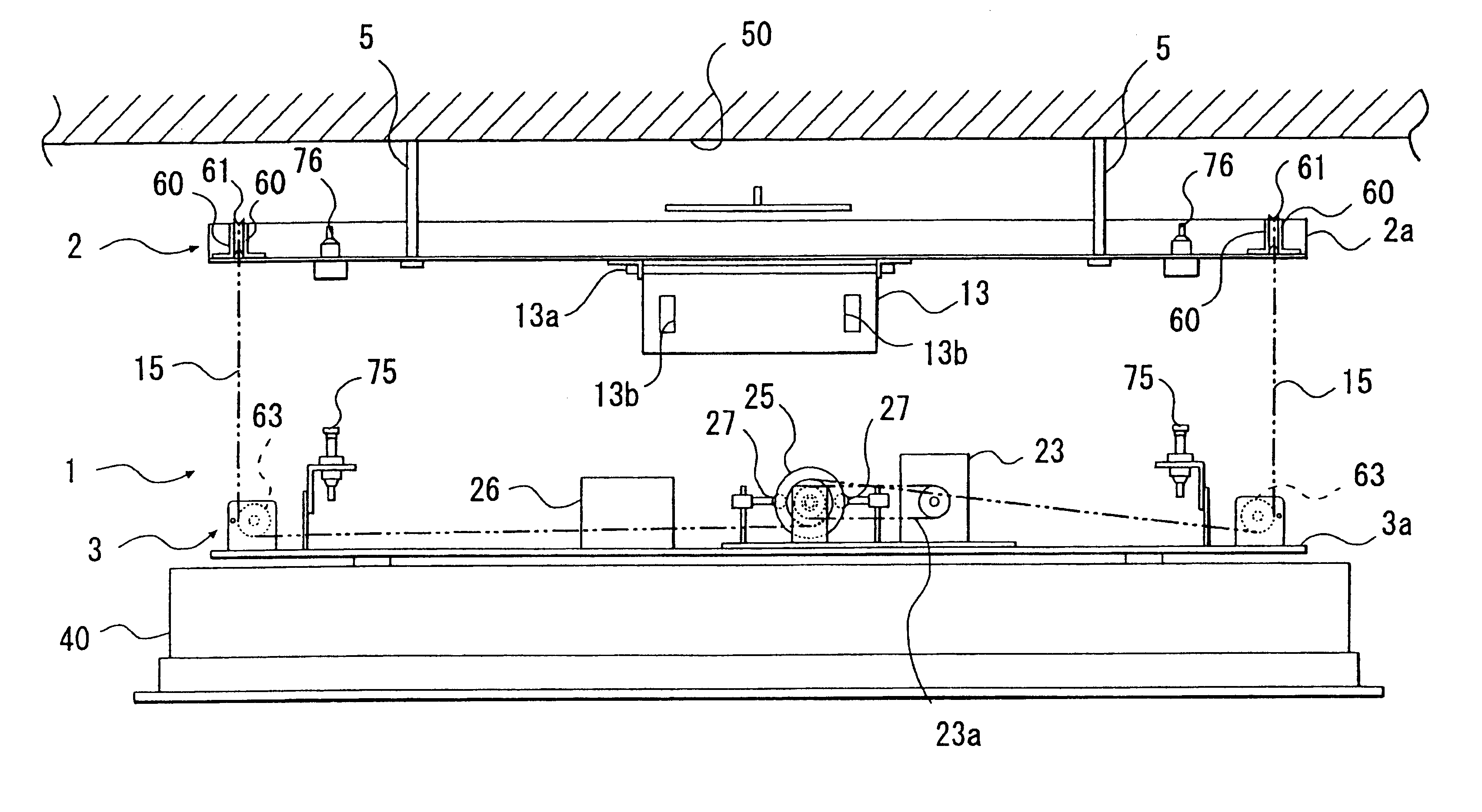
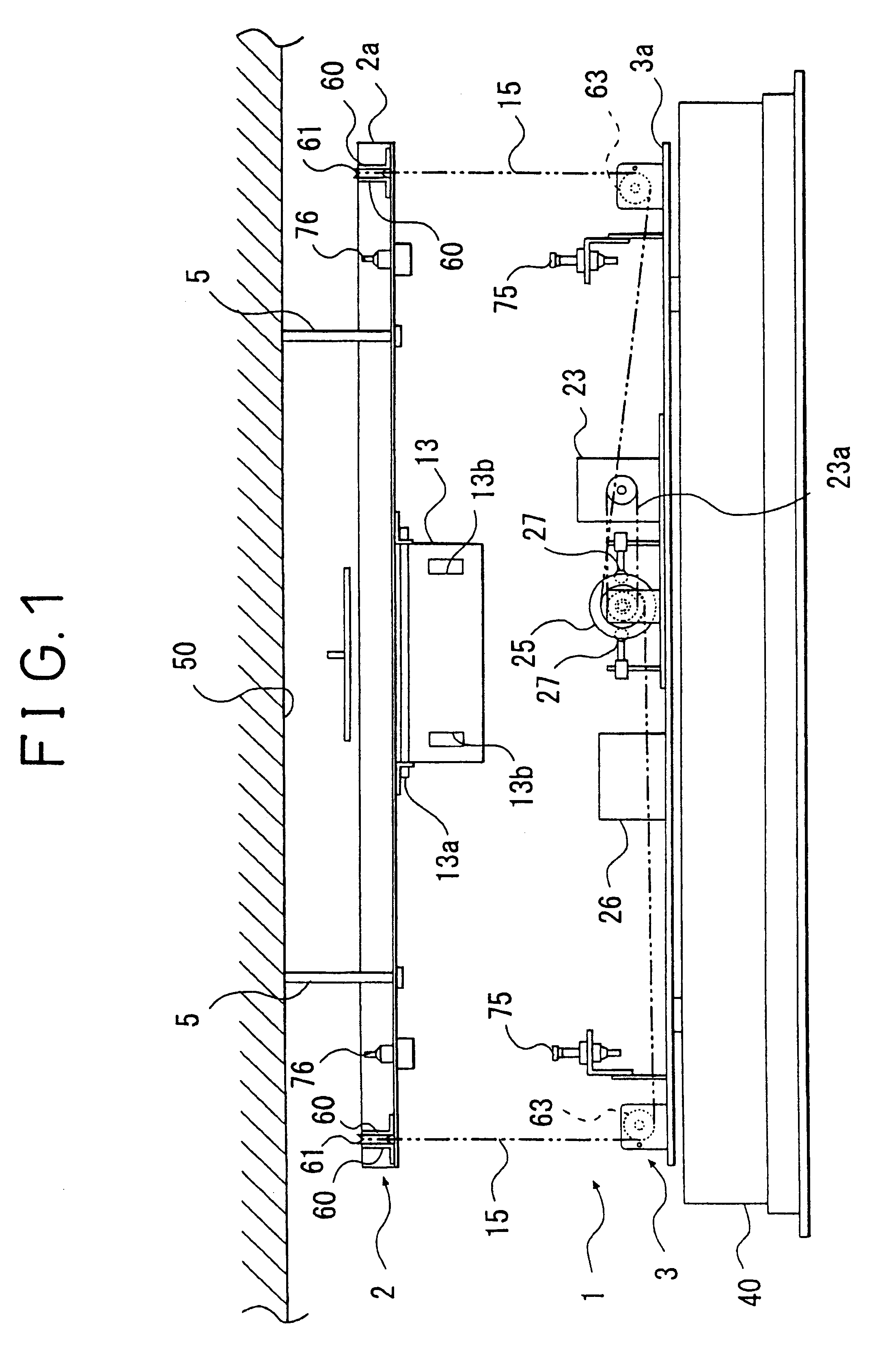
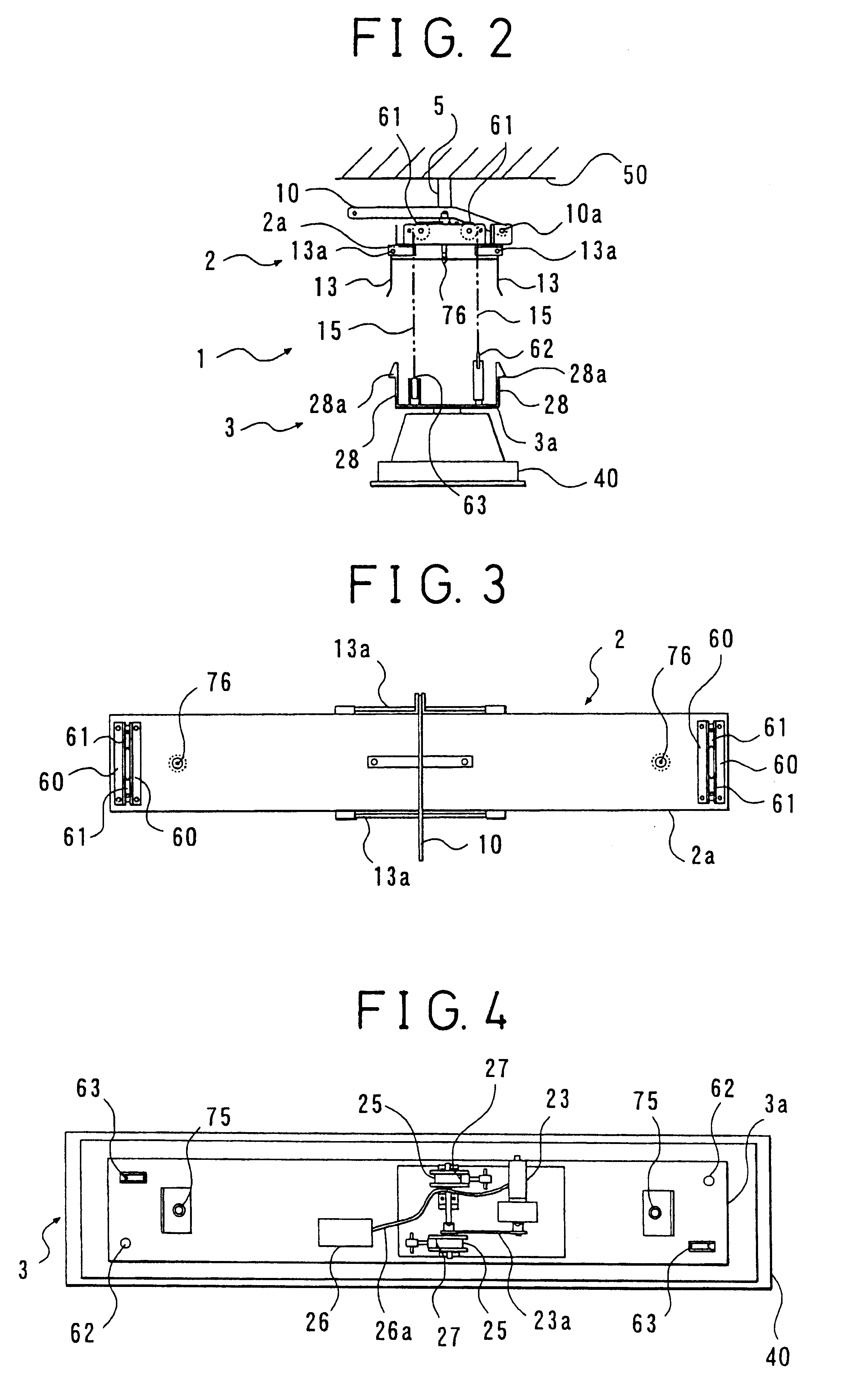
As illustrated in FIGS. 1 and 2, a self-winding-type fixture-lifting / lowering device 1 embodying the present invention comprises a secure block 2 that is securely fixed at an elevated position such as to a ceiling 50, and a lifting / lowering block 3 that hangs from said secure block 2 by means of a pair of wire cables 15 and that is equipped with an elevated-position fixture 40.

In more detail, the secure block 2 includes an upper framework 2a that comprises a plate of an approximately rectangular configuration arranged in a horizontal direction, to which a plurality of rod-like supporting members 5 extend upwards. The upper ends of the supporting members 5 are securely fixed to the ceiling 50.

The lifting / lowering block 3 has a lower framework 3a that comprises a plate of an approximately rectangular configuration arranged in a horizontal direction. On the ...


PUM


Abstract

A self-winding-type fixture-lifting / lowering device comprising a secure block fitted at an elevated position, and a lifting / lowering block that carries a fixture to be installed at an elevated position and that hangs from the secure block by a pair of wire cables in such a manner as to move upwards and downwards, with the lifting / lowering block including an electric motor for lifting operation and a battery for supplying electric power to the electric motor. When the lifting / lowering block reaches the uppermost position, it is kept in position by a lock mechanism, but it can move downwards by its own weight by rotating the electric motor in the reverse direction when the locked feature of the lock mechanism is released.

Description

1. Field of the InventionThe present invention relates to a self-winding-type of device for raising and lowering various types of fixtures, such as lighting fixtures or public-address speaker systems to be installed above the ground at an outdoor field, above the floor in a room, or on the ceiling of a room.2. Related Prior ArtUp to now, when various types of fixtures such as streetlights are to be installed at a raised position, or when such fixtures that have been installed at a raised position require maintenance, generally one of the following three procedures is used: (1) a scaffold is provided; (2) a vehicle designed for working at an elevated position is used; or (3) a lift for maintenance work at a raised position is provided.In the case of a fluorescent-lighting fixture that is installed on a ceiling, for example, a bracket member on the fluorescent-lighting fixture is fixed at the desired position on the ceiling by a fitting means such as fitting screws, and then the main ...

Claims


Application Information

Patent Timeline
IPC IPC(8): F21V21/36F21V21/38
CPCF21V21/38
Inventor ARAMAKI, NORIYOSHI
Owner ARAMAKI TEKUNIKA
Learn More