Miniature electric motor

a miniature electric motor and electric motor technology, applied in the direction of current collectors, dynamo-electric machines, supports/encloses/casings, etc., can solve the problems of difficult to satisfactorily reduce the noise of the motor, troublesome elastic members, and high nois

Inactive Publication Date: 2002-10-15
MABUCHI MOTOR
View PDF22 Cites 25 Cited by
  • Summary
  • Abstract
  • Description
  • Claims
  • Application Information

AI Technical Summary

Benefits of technology

As described above, according to the present invention, it is possible to provide a miniature electric motor which is quiet with low noises even if an elastic member for vibration proof is not used.

Problems solved by technology

However, in the case in which the motor noise is a sound of the frequency within the auditory sensation area and is in particular a high frequency sound (for example, a sound having a frequency of about 10 kHz), the noise becomes a high noisy auditory sound.
However, it is difficult to satisfactorily reduce the motor noise.
Also, when the motor is assembled, the work for mounting the elastic member is troublesome and the number of the motor parts becomes increased.
As a result, the manufacturing steps of the motor are complicated.
Also, unless the elastic member is mounted in a predetermined position with high precision, there are some cases in which the non-uniformity takes place in the extent to reduce the motor noise.
However, this is not used directly for the noise countermeasure by the motor per se.
Also, in some cases, since the elastic member which has been conventionally used is soft, it is difficult to machine the elastic member with high precision, so that non-uniformity in motor noise occurs.

Method used


Image

  • Miniature electric motor
  • Miniature electric motor
  • Miniature electric motor

Examples


Embodiment Construction

One example of the present invention will now be described.

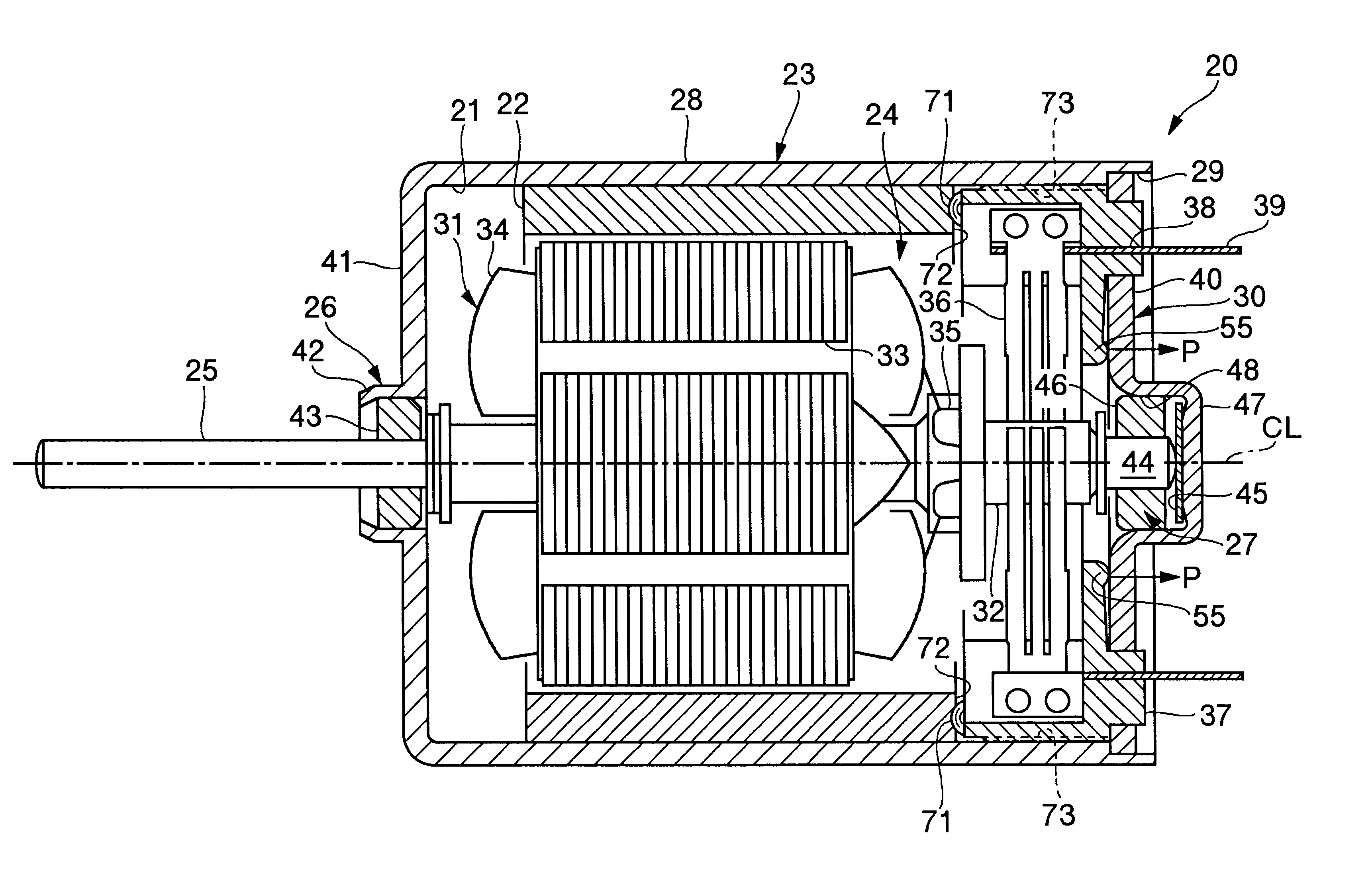
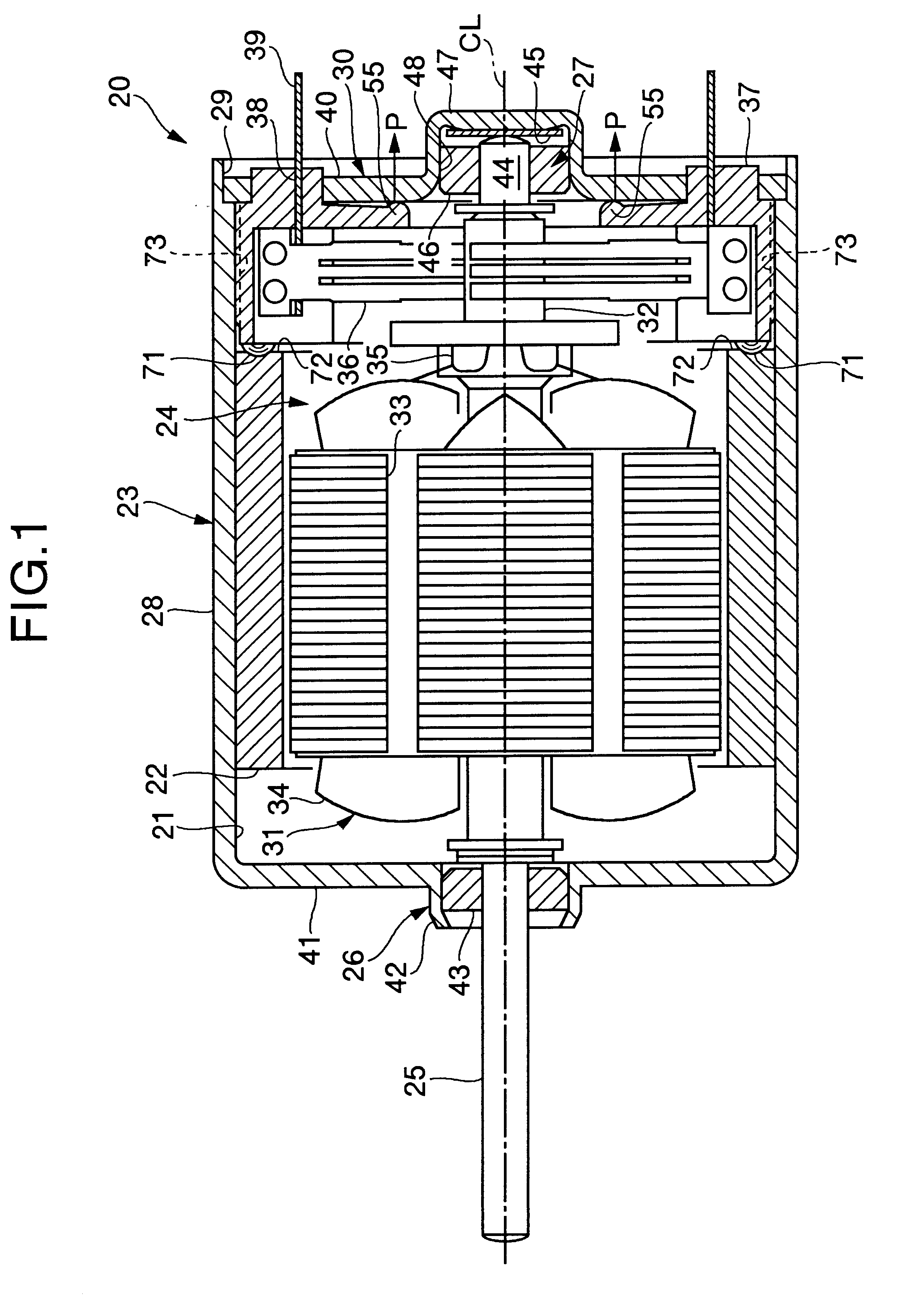
In this example, an experiment was conducted with respect to a conventional miniature electric motor (without any elastic member) M1 and another conventional miniature electric motor (with elastic members) M2 and a miniature electric motor M according to the present invention. The conventional motors M1 and M2 have substantially the same structure as that of the motor shown in FIG. 5. An elastic member for vibration proof is not used in the motor M1. In the motor M2, the gap portions (not shown) are formed at diametrically opposite positions between the brush holder and the housing, and elastic members (not shown) for vibration proof are inserted in these gap portions.

The sizes and the operational conditions of the motors M1, M2 and M used in this experiment are as follows:

Casing diameter: 24 mm

Casing length: 31 mm

Rotary shaft diameter: 2 mm

Revolving speed: about 3,000 min.sup.-1

Output torque: 9.8.times.10.sup.-3 N.multidot....


PUM


Abstract

A miniature electric motor comprises a housing, a cover plate fitted in an opening portion of the housing, a stator fixed to an inner circumferential surface of the housing, a rotor supported rotatably to one and the other bearing portions mounted on the housing and the cover plate, respectively, the rotor being disposed in the housing, and a brush holder holding brushes slidingly engaging with a commutator of the rotor, the brush holder being mounted on the cover plate. A first projection is formed in the vicinity of a center of the brush holder, and the first projection is forcibly pressed at a predetermined pressure against the cover plate. According to the present invention, without using any vibration proof elastic member, it is possible to reduce a noise of the miniature motor and keep the motor quiet. This motor is used for driving an air conditioner of an automobile, or the like.

Description

1. Field of the InventionThe present invention relates to a miniature electric motor. This motor is used for automotive electric equipment such as air conditioners of automobiles, audio visual equipment such as CD (compact disc) players, OA (office automation) equipment such as copying machines, optical precision equipment such as compact cameras, electric equipment for home use, toys or the like.2. Description of the Related ArtA miniature electric motor is extensively used in various fields in addition to the above-specified equipment and is demanded to be quiet by reducing noise of motor.FIG. 5 is a cross-sectional view of a conventional miniature electric motor. In the miniature electric motor 1, a stator 5 is mounted on an inner circumferential surface of a casing 4, having a housing 2 and a cover plate 3. A rotor 6 is disposed in the interior of the casing 4 and a rotary shaft 9 of the rotor 6 is rotatably supported by bearing portions 7 and 8 mounted on the casing 4. Brushes ...

Claims


Application Information

Patent Timeline
Patent Type & Authority Patents(United States)
IPC IPC(8): H02K5/14H02K5/24H02K13/00
CPCH02K5/145H02K5/24
Inventor SHIRAKI, KENJIITAYA, HIDEKI
Owner MABUCHI MOTOR
Why Eureka
Try Eureka