Cryogenic catheter system

Inactive Publication Date: 2002-10-22
MEDTRONIC CRYOCATH LP
View PDF20 Cites 150 Cited by
  • Summary
  • Abstract
  • Description
  • Claims
  • Application Information

AI Technical Summary

Problems solved by technology

In addition, a particular procedure may have to be aborted prematurely without achieving the desired therapeutic effect if the cryocatheter system has insufficient coolant.
However, manually timing the length of a procedure and re

Method used


Image

  • Cryogenic catheter system
  • Cryogenic catheter system
  • Cryogenic catheter system

Examples


Embodiment Construction

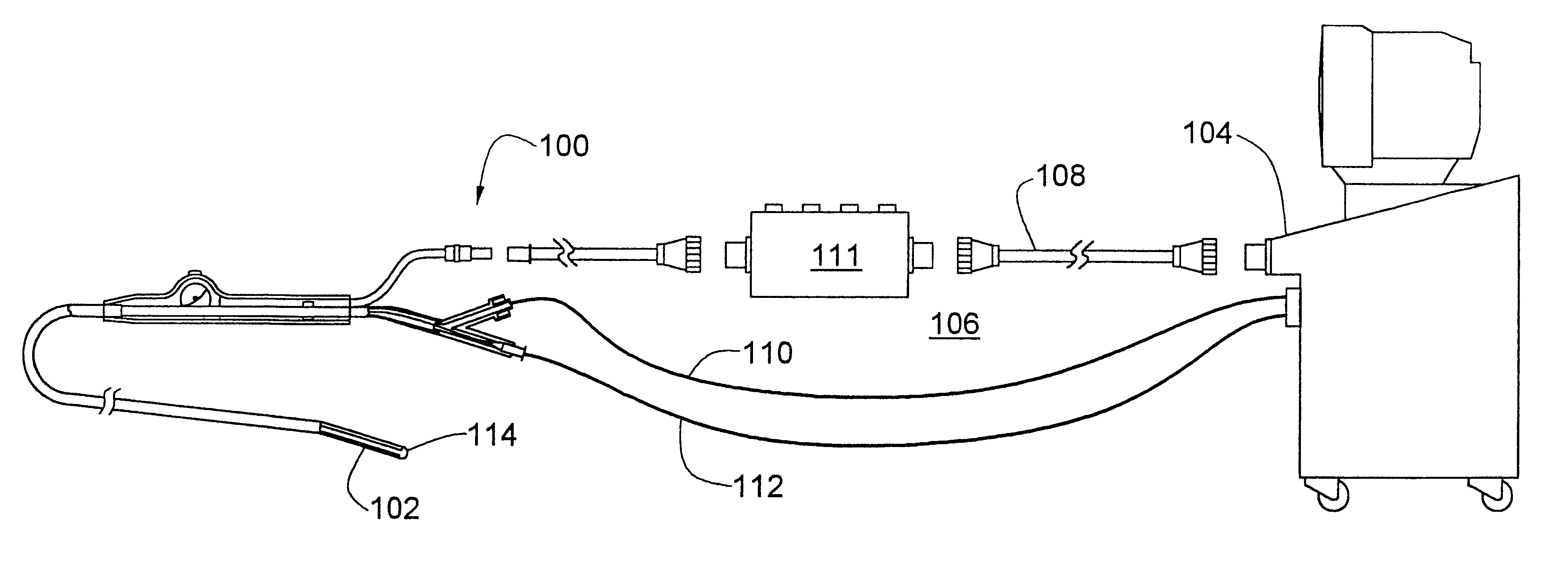
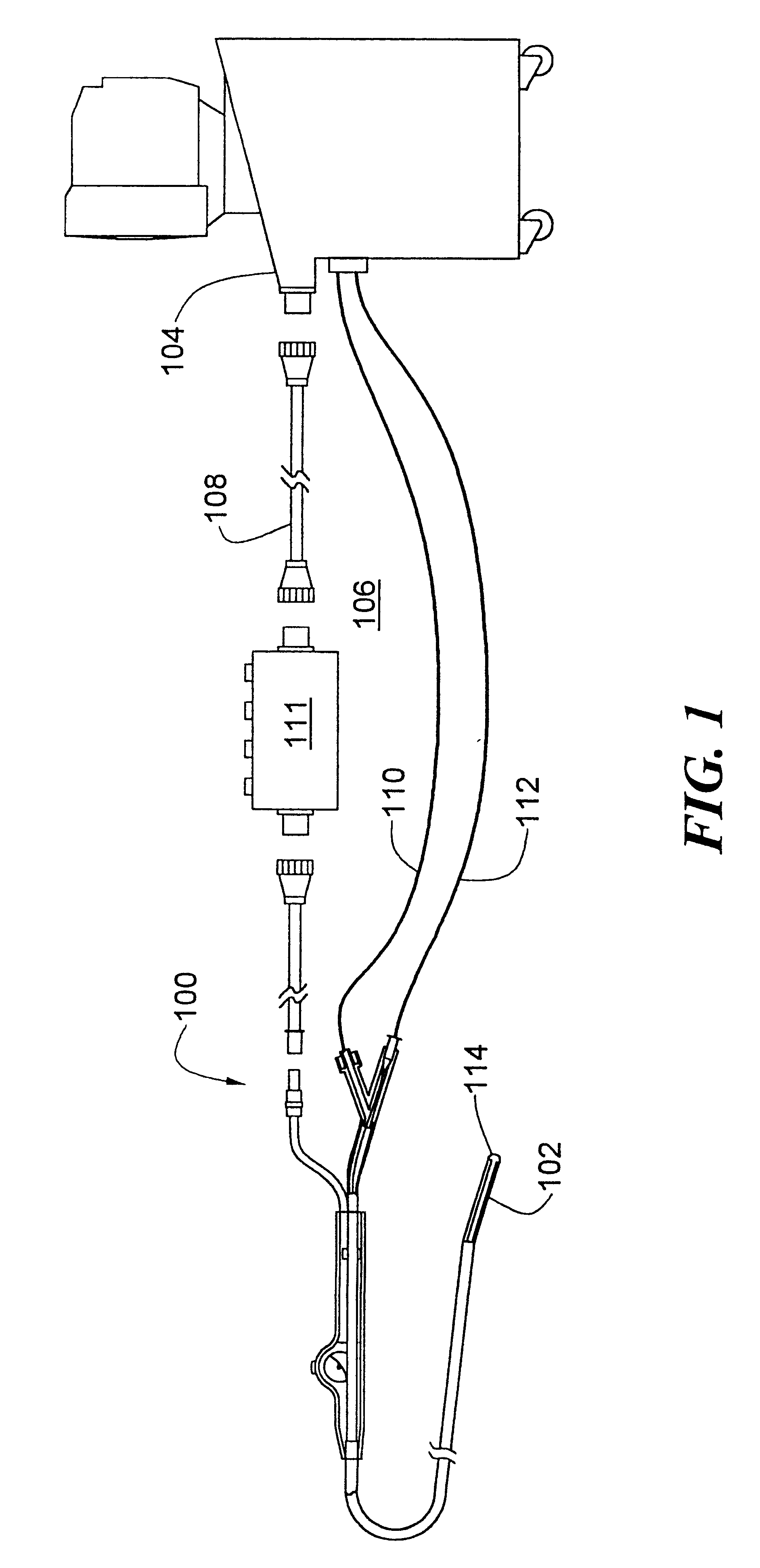
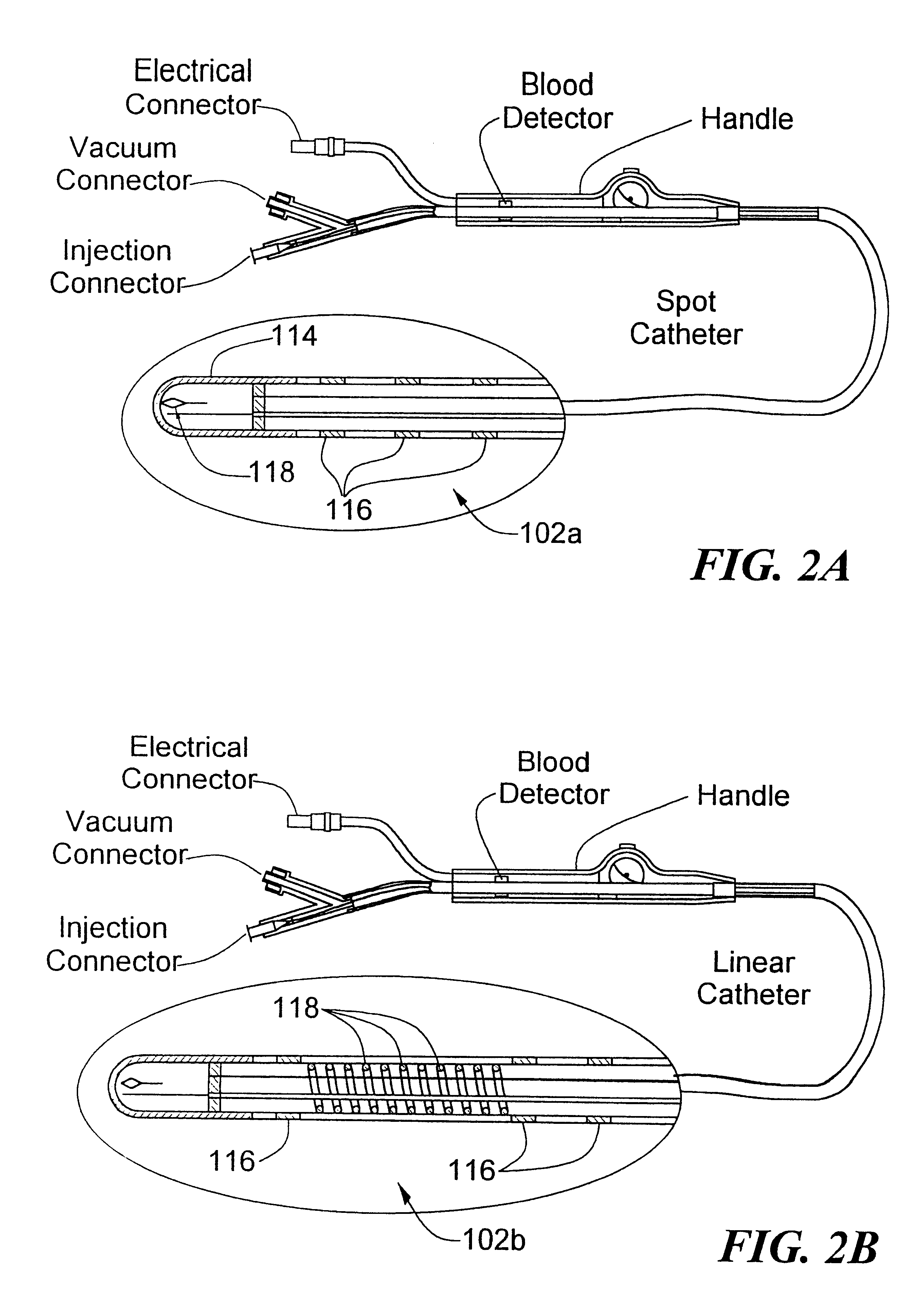
FIG. 1 shows a cryogenic catheter system 100 in accordance with the present invention. The system 100 includes a treatment catheter 102 coupled to a console 104 via an umbilical system 106. The umbilical system includes an electrical umbilical 108 that contains signal lines for cardiac monitoring and / or mapping that are ultimately coupled to a an ECG monitor. The electrical umbilical 108 can include an ECG box 111 to facilitate a connection from ring electrodes 116 (FIGS. 2A-B) to the ECG monitor. A coolant injection umbilical 112 and a coolant vacuum umbilical 110 provide respective inlet and return paths for a refrigerant or coolant used to cool a tissue-treating end 114 of the catheter. The console 104 provides a user interface to the system and houses the electronics and software for controlling and recording the ablation procedure, for controlling delivery of liquid refrigerant under high pressure through the umbilical to the catheter, for controlling the recovery of the expand...


PUM


Abstract

A cryogenic catheter system provides safe and effective treatment of tissue. The system includes a catheter that is coupled to a console via fluid and electrical umbilicals. The console controls the overall operation of the system based to provide and maintain a predetermined temperature at the catheter tip. The console also controls and monitors operating parameters for providing warning indications to the user and terminating operation of the system in the event of a failure that may compromise patient safety.

Description

Not Applicable.1. Field of the InventionThe present invention relates to tissue ablation, and more particularly, to cryogenic catheter systems.2. Background of the InventionMany medical procedures are performed using minimally invasive surgical techniques where one or more slender implements are inserted through a small incision into a patient's body. Minimally, invasive surgical implements for ablating tissue can include a rigid or flexible structure having an ablation device at or near its distal end that is placed adjacent to the tissue to be ablated.There are many procedures that include ablating certain tissue. For example, cardiac arrhythmias can be treated through selective ablation of cardiac tissue to eliminate the source of the arrhythmia. One type of minimally invasive procedure includes the use of an ablation catheter subsequent to a preliminary step of electrocardiographic mapping. After examination of the mapping results, one or more ablated regions (lesions) are creat...

Claims


Application Information

Patent Timeline
IPC IPC(8): A61B18/18A61B17/00A61B18/02A61B18/04A61F7/00
CPCA61B18/02A61B2017/00092A61B2017/00119A61B2018/0212A61B2018/0262A61F7/12
Inventor ABBOUD, MARWANAL ASMAR, JOHNNYLALONDE, JEAN-PIERRE
Owner MEDTRONIC CRYOCATH LP
Why Eureka
Try Eureka