Switching power supply device having series capacitance

a power supply device and capacitance technology, applied in the direction of power conversion systems, dc-dc conversion, instruments, etc., can solve the problems of affecting the miniaturization of the device and cost reduction, the increase in the loss of the control circuit, and the dc-dc conversion

Inactive Publication Date: 2002-10-22
MURATA MFG CO LTD
View PDF15 Cites 43 Cited by
  • Summary
  • Abstract
  • Description
  • Claims
  • Application Information

AI Technical Summary

Benefits of technology

In this case, by setting the ON-time of the switching element to be a minimum value or greater to perform switching even in the state in which the load is short-circuited, the switching operation can be continued even in the short-circuited state. Therefore, when the short-circuited state is cleared, the output is applied to the load again automatically. Thus, an overcurrent protective circuit of a self-recovery type capable of restoring output can be formed. When an ON-time equivalent to a value equal to or less than the minimum value is set, under a short-circuited load, an input voltage is applied to the capacitor C and the oscillation thereby stops, whereby a latch-type overcurrent protective circuit is formed.

Problems solved by technology

In each of the switching power supply devices above, however, there are problems as follows.
As a result, there are problems such as interference with electronic components and increase in loss in the control circuits.
Additionally, since the switching power supply device is a separately excited oscillation type of device, the number of components increases, which hinders miniaturization of the device and cost reduction.
However, each of the devices is not a self-excited oscillation type but a separately excited oscillation type or a synchronous oscillation type.
Thus, since the device requires an oscillator, a drive circuit, and the like, the number of components increases, thereby hindering miniaturization of the device and cost reduction.
As a result, in even the switching power supply device, the size of the switching control circuit and production cost increase.
In addition, since the power supply device has a structure in which the input voltage Vin is directly applied to the primary winding T1 of a transformer T, the voltage applied to the primary winding T1 becomes higher, which hinders miniaturization of the device.
As a result, a peak current value of the primary winding becomes larger, thereby increasing conduction loss.

Method used


Image

  • Switching power supply device having series capacitance
  • Switching power supply device having series capacitance
  • Switching power supply device having series capacitance

Examples


Embodiment Construction

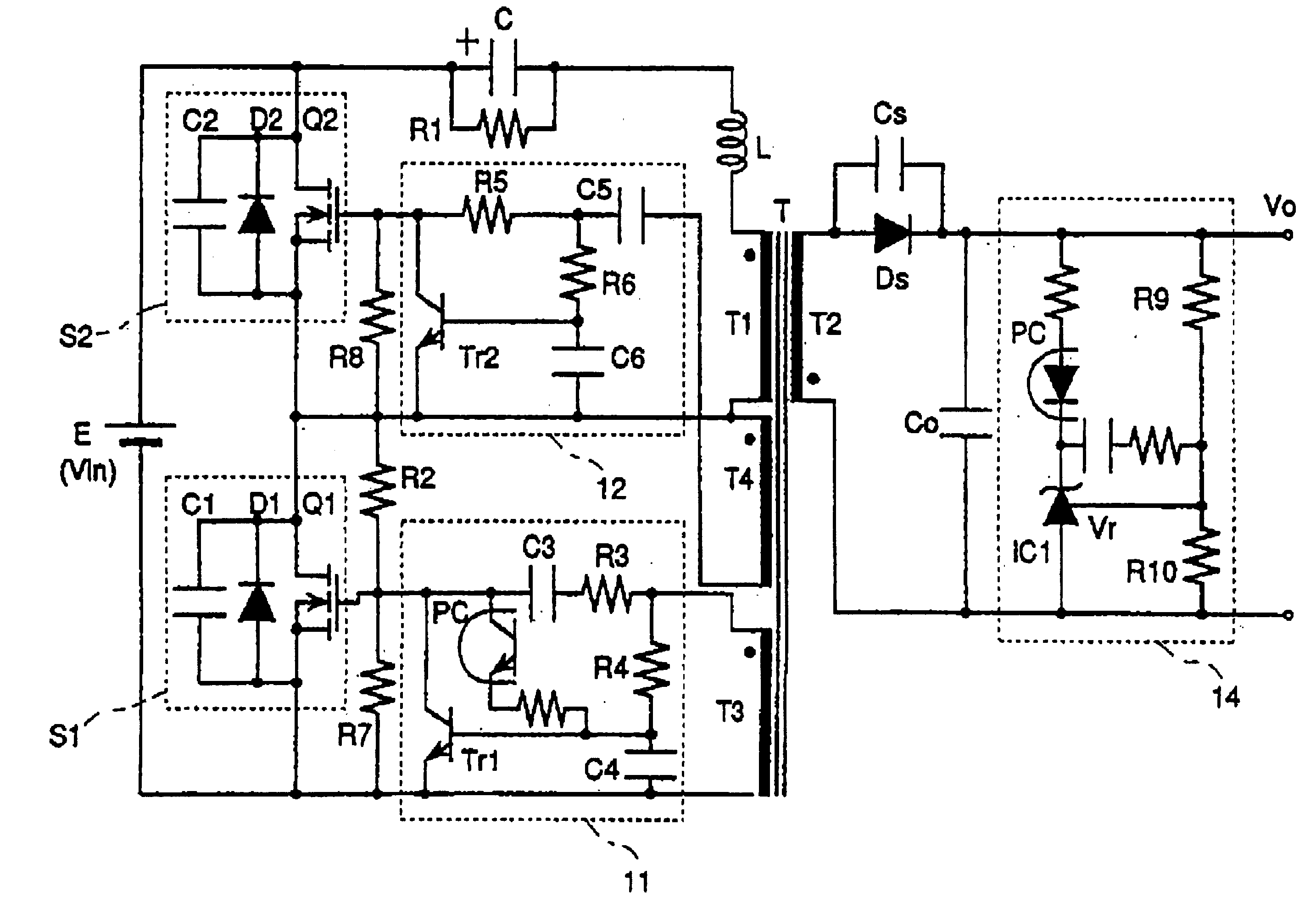
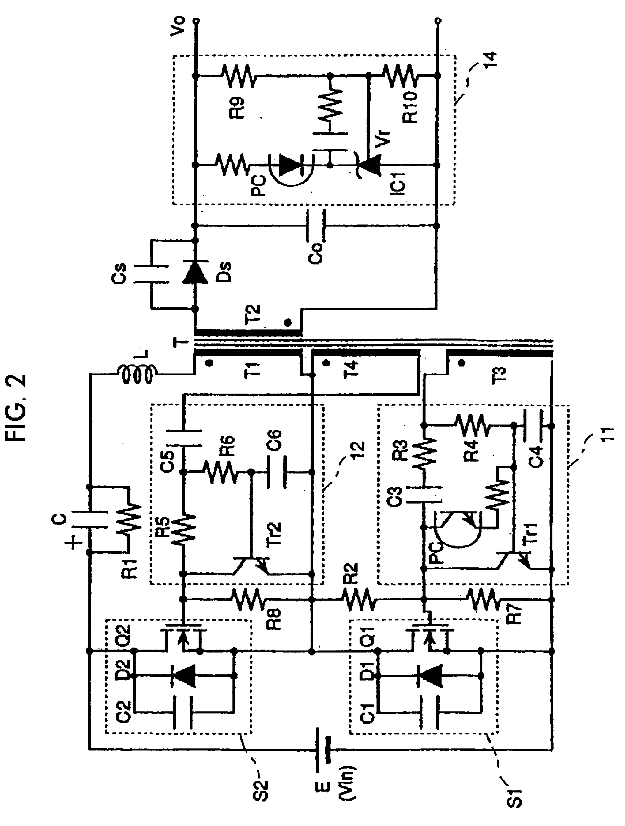
FIG. 2 is a circuit diagram of a switching power supply device according to an embodiment of the present invention.

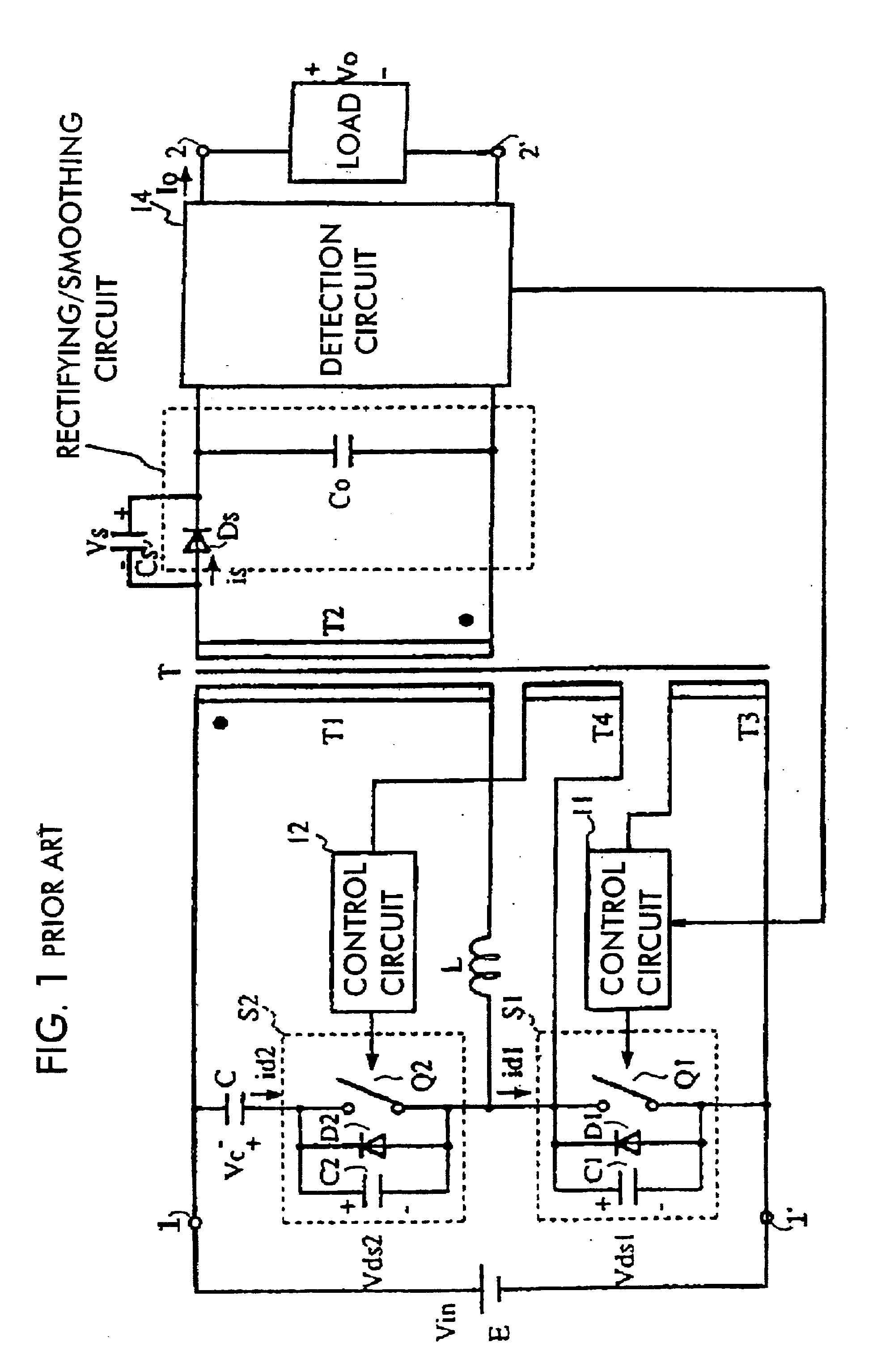
Basically, the switching power supply device of the embodiment differs from the conventional switching power supply device shown in FIG. 1 by including a series circuit formed by connecting a primary winding T1 of a transformer T, an inductor L, and a capacitor C, one end of the series circuit being connected to a junction of a first switching circuit and a second switching circuit and the other end thereof being connected to an input power source. Next, the circuit structure of the switching power supply device will be explained in detail.

The first switching circuit S1 is formed by a parallel connection circuit of a first switching element Q1, a first diode D1, and a first capacitor C1. The second switching circuit S2 is formed by a parallel connection circuit of a second switching element Q2, a second diode D2, and a second capacitor C2. The first and second switching...


PUM


Abstract

A switching power supply device that can reduce switching loss to obtain high efficiency. Additionally, the number of components of control circuits and the cost of switching elements can be reduced, with a transformer made compact and lightweight. In this switching power supply device, one end of a series circuit comprising a primary winding of the transformer, an inductor, and a capacitor is connected to a junction of a first switching circuit and a second switching circuit. The other end of the series circuit is connected to an input power source. A secondary winding of the transformer is connected to a rectifying and smoothing circuit including a rectifying element. In addition, in order to perform a self-excited oscillation, there are arranged first and second control circuits. The first control circuit controls a time elapsing until the first switching circuit turns on after the generation of a voltage in a first driving winding of the transformer and a time elapsing until the first switching circuit turns off. Similarly, the second control circuit controls a time elapsing from the generation of a voltage in a second driving winding of the transformer to the turn-on of the second switching circuit and a time elapsing until the second switching circuit turns off.

Description

1. Field of the InventionThe present invention relates to switching power supply devices for supplying DC stabilizing voltages. More particularly, the invention relates to switching power supply devices storing energy in the primary winding of a transformer and a capacitor during the ON-periods of a switching element and supplying the stored energy to a load from the secondary winding of the transformer during the OFF-periods of the switching element.2. Description of the Related ArtIn Japanese Patent Application No. 9-352696, there is provided a switching power supply device, in which a first switching circuit is connected to a second switching circuit on the primary winding side of a transformer T and switching control circuits alternately turn on and off switching elements included in the first and second switching circuits before and after periods during which both switching elements are turned off so that a self-excited oscillation is performed. FIG. 1 is a block diagram illust...

Claims


Application Information

Patent Timeline
Patent Type & Authority Patents(United States)
IPC IPC(8): H02M3/24H02M3/338H02M3/28H02M3/335
CPCH02M3/3382
Inventor HOSOTANI, TATSUYATAKEMURA, HIROSHIOKAMOTO, YASUJI
Owner MURATA MFG CO LTD
Why Eureka
Try Eureka