Filter unit comprising a wideband bandpass filter and one band-elimination filter

a filter unit and wideband bandpass technology, applied in the field of filter units, duplexers, communication devices, can solve the problem of increasing the manufacturing cost of filter units

Inactive Publication Date: 2002-10-22
MURATA MFG CO LTD
View PDF4 Cites 36 Cited by
  • Summary
  • Abstract
  • Description
  • Claims
  • Application Information

AI Technical Summary

Problems solved by technology

Because of this, the filter unit becomes large-sized and the soldering work for mounting the bandpass filter units, and so on, increases, and accordingly there is the problem that the manufacturing cost of the filter unit increases.

Method used


Image

  • Filter unit comprising a wideband bandpass filter and one band-elimination filter
  • Filter unit comprising a wideband bandpass filter and one band-elimination filter
  • Filter unit comprising a wideband bandpass filter and one band-elimination filter

Examples


first embodiment

, FIGS. 1 through 6

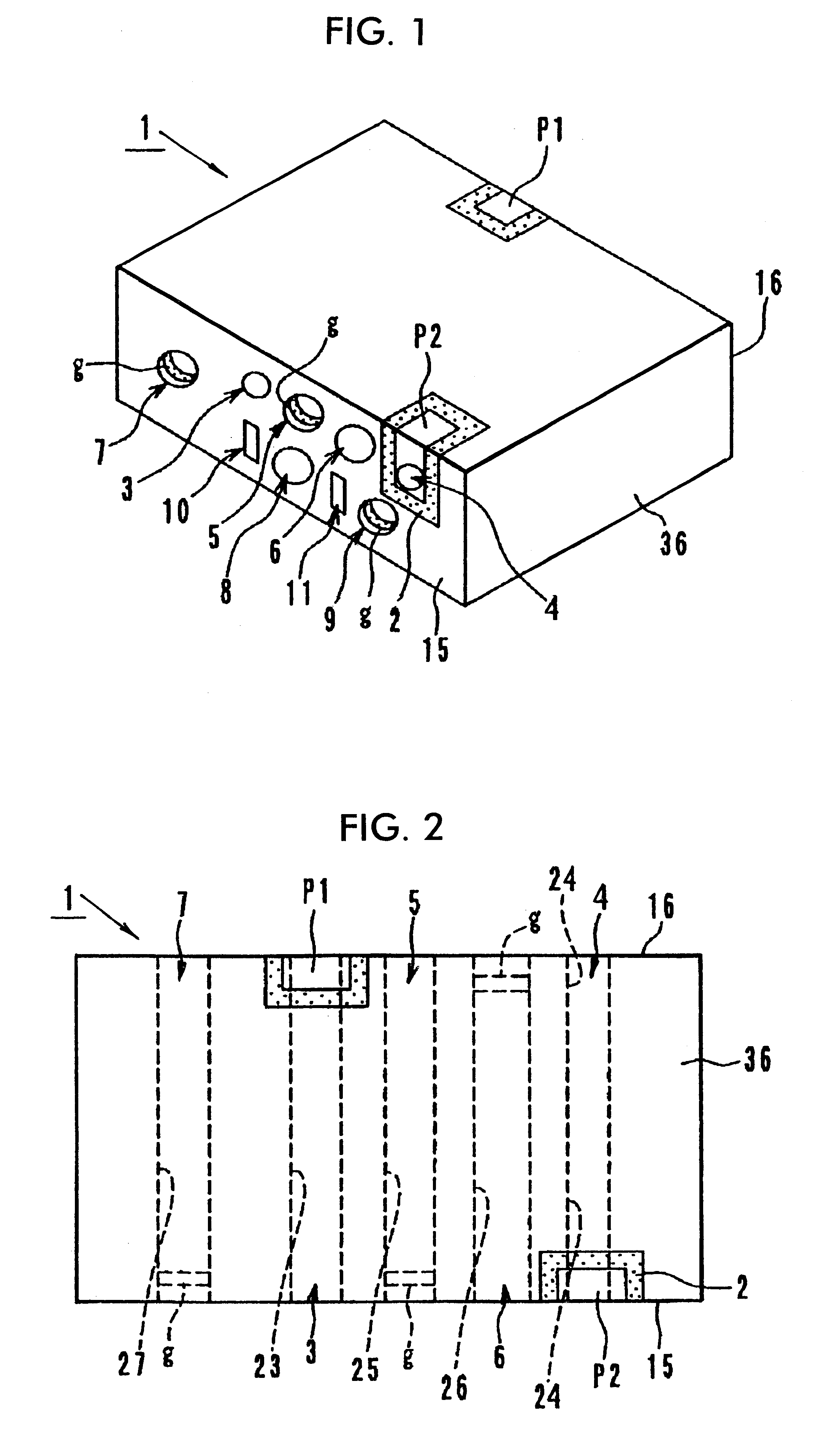
Referring to FIG. 1, the filter unit 1 contains one wideband bandpass filter and three band-elimination filters. In a dielectric member (a dielectric block) 2 in the form of a rectangular solid with an outer conductor 36, input-output coupling resonator holes 3 and 4, resonator holes 5 through 9, and grounding holes 10 and 11 are provided.

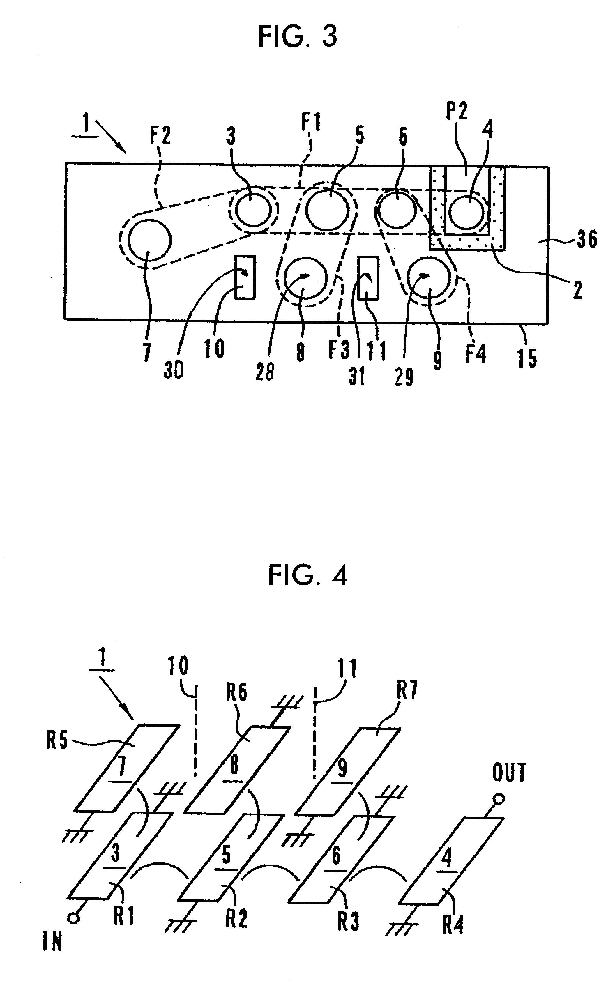
Each of the resonator holes 3 through 9 and grounding holes 10 and 11 pass from a first surface 15 of the dielectric block 2 completely through to a second surface 16 opposite to the first surface, as shown in FIG. 2. (The resonator holes 8 and 9, and grounding holes 10 and 11, are omitted from FIG. 2, but are shown in FIG. 3.) The resonator holes 3 through 9 and grounding holes 10 and 11 are straight holes each having a constant internal diameter, and on their internal wall surfaces inner conductors 23 through 29, and 30 and 31 are formed, respectively. (Inner conductors 28-31 are shown schematically in FIG. 3.) In the inner con...

second embodiment

, FIGS. 7 and 8

Another embodiment of a filter unit according to the present invention is shown in FIG. 7. The filter unit 41 is made up of a dielectric member (a dielectric sheet) 42a on the surface of which strip lines 43, 44, 45, and 46 are formed, and a dielectric member (a dielectric sheet) 42b on the surface of which strip lines 47, 48, and 49 are formed, and a pair of dielectric members (protective dielectric sheets) 42c, are disposed respectively on opposite sides of the dielectric members 42a and 42b.

In the strip lines 43 and 44, the end portions 43a and 44a are exposed at the front side of the sheet 42a and the end portions 43b and 44b are exposed at the back side of the sheet 42a. In the strip line 45, one end portion 45a is exposed at the front side of the sheet 42a. In the strip line 46, one end portion 46a is exposed at the back side of the sheet 42a. In the strip lines 47 and 49, end portions 47a and 49a are exposed at the front side of the sheet 42b. In the strip line...

third and fourth embodiments

, FIGS. 9 and 10

FIG. 9 shows the electric circuit diagram of a third embodiment of a filter unit according to the present invention. The filter unit 61 is made up of one wideband bandpass filter F5 and three band-elimination filters F6, F7, and F8.

The wideband bandpass filter F5 is realized by a four-stage coupling of resonators R11, R12, R13, and R14 through coupling coils L1, L2, and L3. This wideband bandpass filter F5 is electrically connected between input-output terminals P3 and P4 through coupling capacitors C1 and C2.

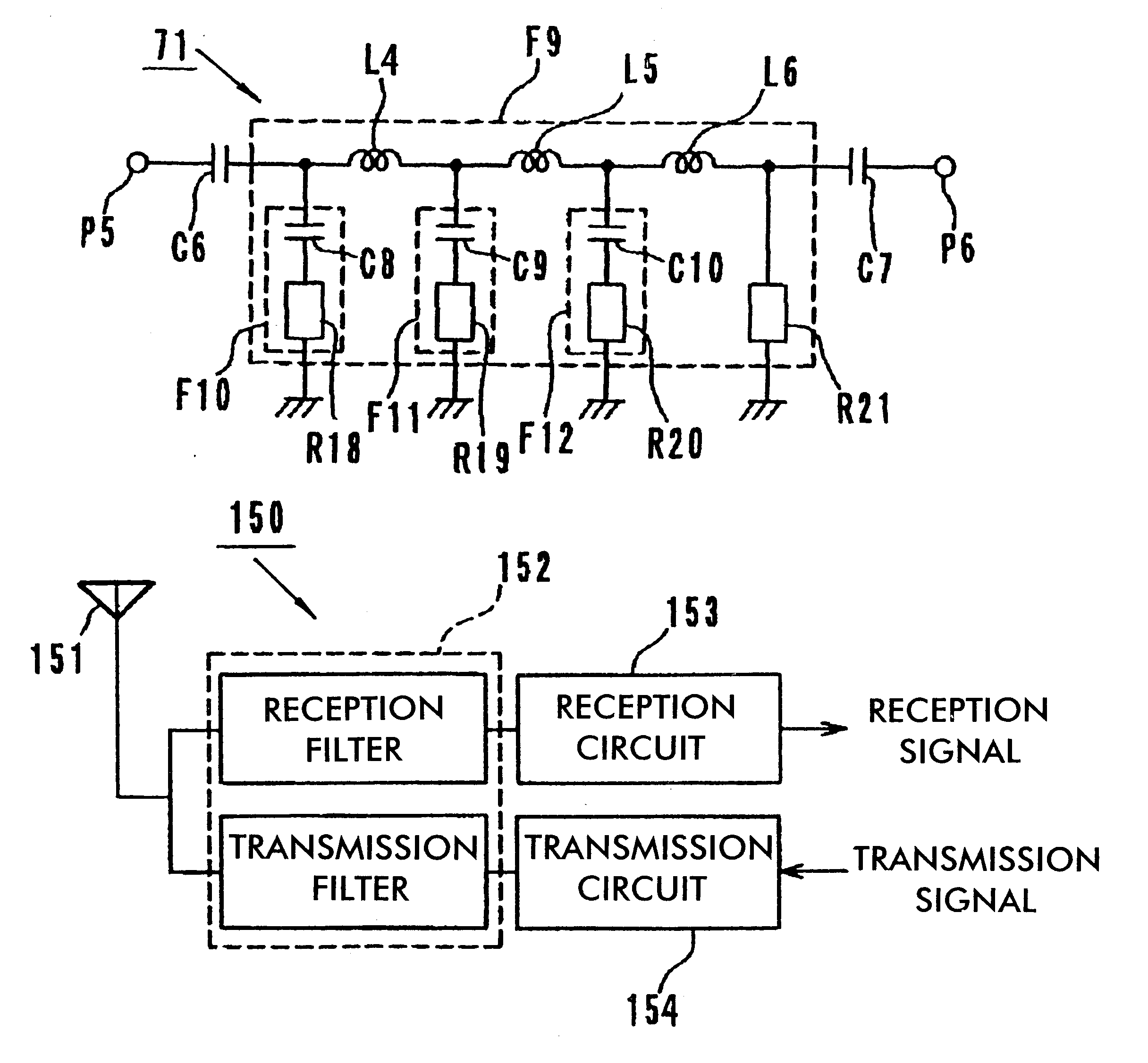
The band-elimination filter F6 is composed of a series resonance circuit of a resonance capacitor C3 and a resonator R15. In the same way, the band-elimination filter F7 is composed of a series resonance circuit of a resonance capacitor C4 and a resonator R16, and the band-elimination filter F8 is composed of a series resonance circuit of a resonance capacitor C5 and a resonator R17. The resonance capacitors C3 through C5 determine the extent of attenuation in t...


PUM


Abstract

A filter unit comprises a wideband bandpass filter; at least one band-elimination filter having a stop band within the passband of the bandpass filter, so that the passband is divided into a plurality of pass bands by the stop band; and the wideband bandpass filter and the band-elimination filter being disposed in a single dielectric member. Since the passband of a wideband bandpass filter is divided into a plurality of pass bands by stop bands of one or more band-elimination filters, signals having frequencies corresponding to these divided pass bands are able to pass through the filter unit simultaneously.

Description

1. Field of the InventionThe present invention relates to a filter unit, duplexer, and communication apparatus for use in microwave frequency bands, for example.2. Description of the Related ArtUp to now, filter units which allow two or more frequency bands to pass through at the same time have been composed of two or more bandpass filter units electrically connected in parallel. For example, in the case of a filter unit 91 allowing two frequency bands fa and fb to pass through simultaneously as shown in FIG. 13, a bandpass filter unit F21 allowing a frequency band fa to pass through and a bandpass filter unit F22 allowing a frequency band fb to pass through are electrically connected in parallel. FIG. 14 shows a filtering characteristic curve of the filter unit obtained in this way.However, in the prior art filter unit, it is required to connect electrically in parallel the same number of bandpass filter units as the number of frequency bands to be allowed to pass through. Therefor...

Claims


Application Information

Patent Timeline
Patent Type & Authority Patents(United States)
IPC IPC(8): H01P1/203H03H7/01H03H7/06H01P1/205H01P1/20H04B1/52H04B1/50H01P1/213
CPCH01P1/20345H01P1/2056H03H7/0123H03H7/1758H03H7/1791H04B1/52H03H7/075H03H2001/0085
Inventor OKADA, TAKAHIROISHIHARA, JINSEIKATO, HIDEYUKI
Owner MURATA MFG CO LTD
Why Eureka
Try Eureka