Balanced rotary servovalve

a rotary servo valve and balance technology, applied in the direction of valve operating means/release devices, pressure relieving devices on sealing faces, transportation and packaging, etc., can solve the problems of slow response, internal pressure imbalance in a conventional rotary fluid valve, and need for greater operating energy

Inactive Publication Date: 2002-10-29
WOODWORTH RAYMOND D
View PDF13 Cites 34 Cited by
  • Summary
  • Abstract
  • Description
  • Claims
  • Application Information

AI Technical Summary

Problems solved by technology

Since the fluid flow passageway within the valve which conducts fluid from the high pressure fluid source is typically located on the opposite side of the valve from the fluid passageway that conducts fluid to the fluid reservoir, there is an imbalance in internal pressure within a conventional rotary fluid valve.
This results in a slower response and a need for greater operating energy in the solenoid actuator for the solenoid operated rotary valve.
This force imbalance creates a greater friction within the valve and necessitates the use of a higher torque motor than would otherwise be necessary to operate the valve if the valve were properly balanced.

Method used


Image

  • Balanced rotary servovalve
  • Balanced rotary servovalve
  • Balanced rotary servovalve

Examples


Embodiment Construction

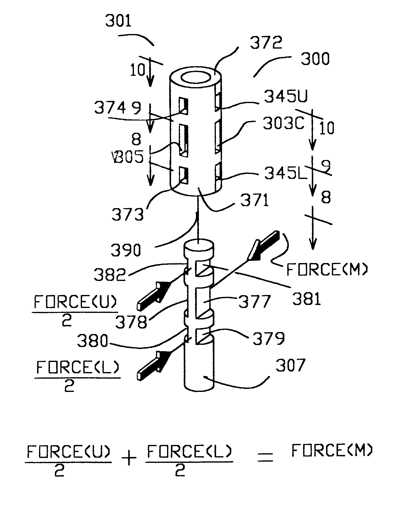
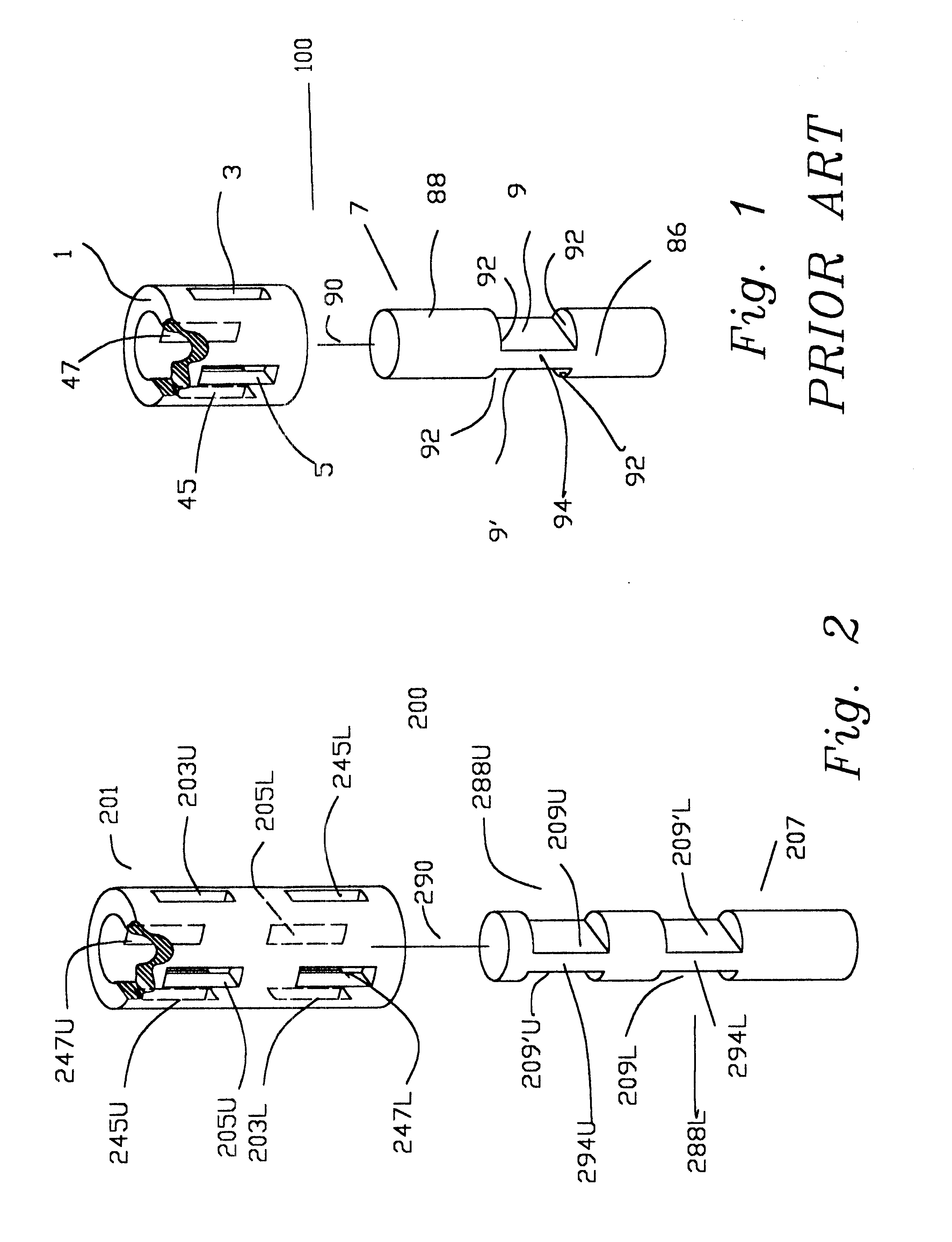
FIG. 1 is a diagrammatic illustration of the mechanical components of a rotary servovalve 100 which may be utilized in a rotary solenoid actuated system as illustrated and described in U.S. patent application Ser. No. 09 / 430,880 filed Nov. 1, 1999, which application is incorporated herein by reference in its entirety. FIG. 2 is a diagrammatic illustration of the mechanical components of one embodiment of a servovalve according to the present invention which may be used in place of the valve shown in FIG. 1.

FIG. 1 illustrates the movable valve gate element 7 and the valve housing sleeve 1 (partially broken away) of a conventional rotary servovalve 100 in enlarged detail. The valve housing sleeve 1 is formed of hardened steel and contains four longitudinally elongated, precision, rectangular shaped fluid passageways or openings 3, 5, 45, and 47. The valve housing sleeve 1 of the rotary valve 100 has a single inlet orifice 47, a single outlet orifice 5, a single first fluid transfer or...


PUM


Abstract

A rotory servovalve is constructed with a cylindrical annular housing and a cylindrical valve element rotatable therewithin. The valve housing has at least two inlet orifices, at least two outlet orifices, at least two first fluid transfer control orifices, and at least two second fluid transfer control orifices. At least two orifices of each type are located on opposite sides of the valve housing from each other. Preferably there is a first end orifice, a central orifice, and a second end orifice of each type. The end orifices of each type are angularly and longitudinally aligned with each other and are angularly offset 180 degrees from a central orifice of the same type. The end orifices of each type have an area equal to one-half the area of the central orifice of the same type and are equally spaced in opposite longitudinal directions from the central orifice of the same type. An imbalance of fluid forces within the servovalve mechanism is thereby avoided, both in a direction perpendicular to the valve axis and in planes passing through and containing the valve axis. By eliminating force imbalances within the valve in high-pressure applications the electrical current requirement and the mass of the components required for the driving motor or rotory solenoid that operates the valve are reduced.

Description

1. Field of the InventionThe present invention relates to rotary servovalves, and in particular to high speed rotory servovalves, used to control the flow of fluids under high-pressure, particularly liquids.2. Description of the Prior ArtMany different mechanical and electrical servovalve systems have been employed for controlling fluid flow in industrial and manufacturing environments, as well as in other applications. Fluid servovalve control systems which require precise and highly responsive control are employed in a multitude of widely varying applications, including the control of robots, the operations of presses for manufacturing rubber and plastic parts, the control of tensioning devices in the paper industry, automotive vehicle and parts manufacturing, petroleum refining operations, and numerous other applications.In many of the applications in which servo control valve systems are utilized, pressurized fluid is typically provided from a high pressure source and transmitte...

Claims


Application Information

Patent Timeline
Patent Type & Authority Patents(United States)
IPC IPC(8): F15B13/00F15B13/04F16K31/04F16K11/085F16K11/02
CPCF15B13/0406F16K11/085F16K31/041F15B2013/0409Y10T137/86654
Inventor WOODWORTH, RAYMOND D.
Owner WOODWORTH RAYMOND D
Why Eureka
Try Eureka