Slips for drill pipes or other tubular members

a technology for drilling pipes and tubular parts, which is applied in the direction of mechanical equipment, manufacturing tools, and rod connections, etc., can solve the problems of slipping segments in the critical "nose, affecting the stability of the drill shaft,

Inactive Publication Date: 2002-10-29
ALLAMON INTEREST
View PDF207 Cites 67 Cited by
  • Summary
  • Abstract
  • Description
  • Claims
  • Application Information

AI Technical Summary

Benefits of technology

Second, slip segments in accordance with the present invention are fabricated from forged steel. By using forged steel components, the slip segments function with more durability and with greater load bearing capacity than prior art slip segments fabricated from castings.
Third, in accordance with the present invention, each die in the lowermost set of hardened dies is fabricated having a rounded bottom end with a tapered profile. The rounded end and tapered profile match the shape of the bottom of the axial grooves. This provides full support to the bottom of the lowermost set of hardened dies and precludes the need to weld half-moon inserts to the bottom of the axial grooves.

Problems solved by technology

The hardened dies are necessary because the contact stresses with the pipe can be quite high and the dies are subject to considerable wear.
As a result of the high repeated loads experienced in many of the deep well applications, bothersome cracking has been noted in the slip segments in the critical "nose" areas that support the loads from the dies.
If these cracks are allowed to grow to the point of complete failure to support the dies, the result could be the loss of the drill string downhole as well as loss of the suspended load.
This could result in huge remedial costs, or complete loss of the well.
Such gaps may yield an unbalanced loading condition among the dies.
Even with the apparatus as described in the '489 Application, however, some nose cracking has still been observed due to lateral stresses along the nose area of the drill slip segments.
These stresses create cracks along the nose area of the drill slip and cause drilling operators to replace the slips prematurely to avoid a failure of the slip entirely and resulting damage to the drill pipe and possibly the well.
However, weld failures have been observed on the half-moon inserts during loading operations causing the lowermost set of dies to lose structural support.

Method used


Image

  • Slips for drill pipes or other tubular members
  • Slips for drill pipes or other tubular members
  • Slips for drill pipes or other tubular members

Examples


Embodiment Construction

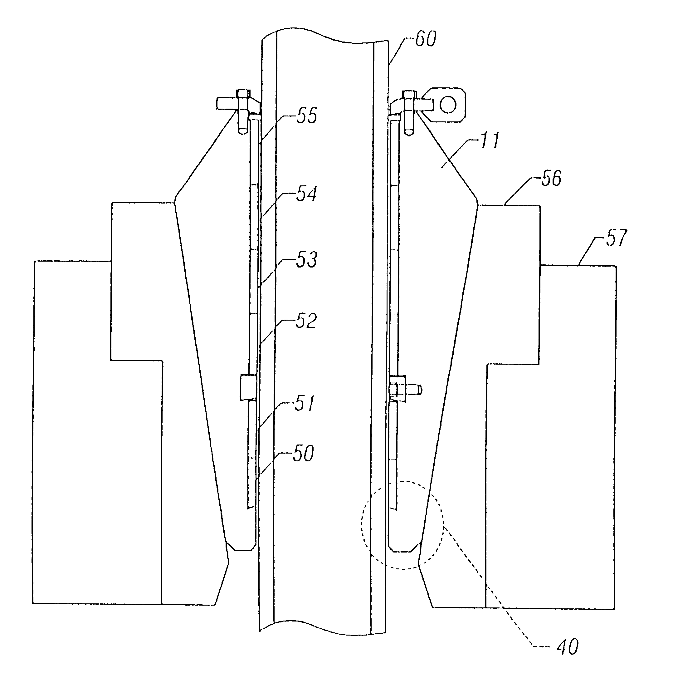
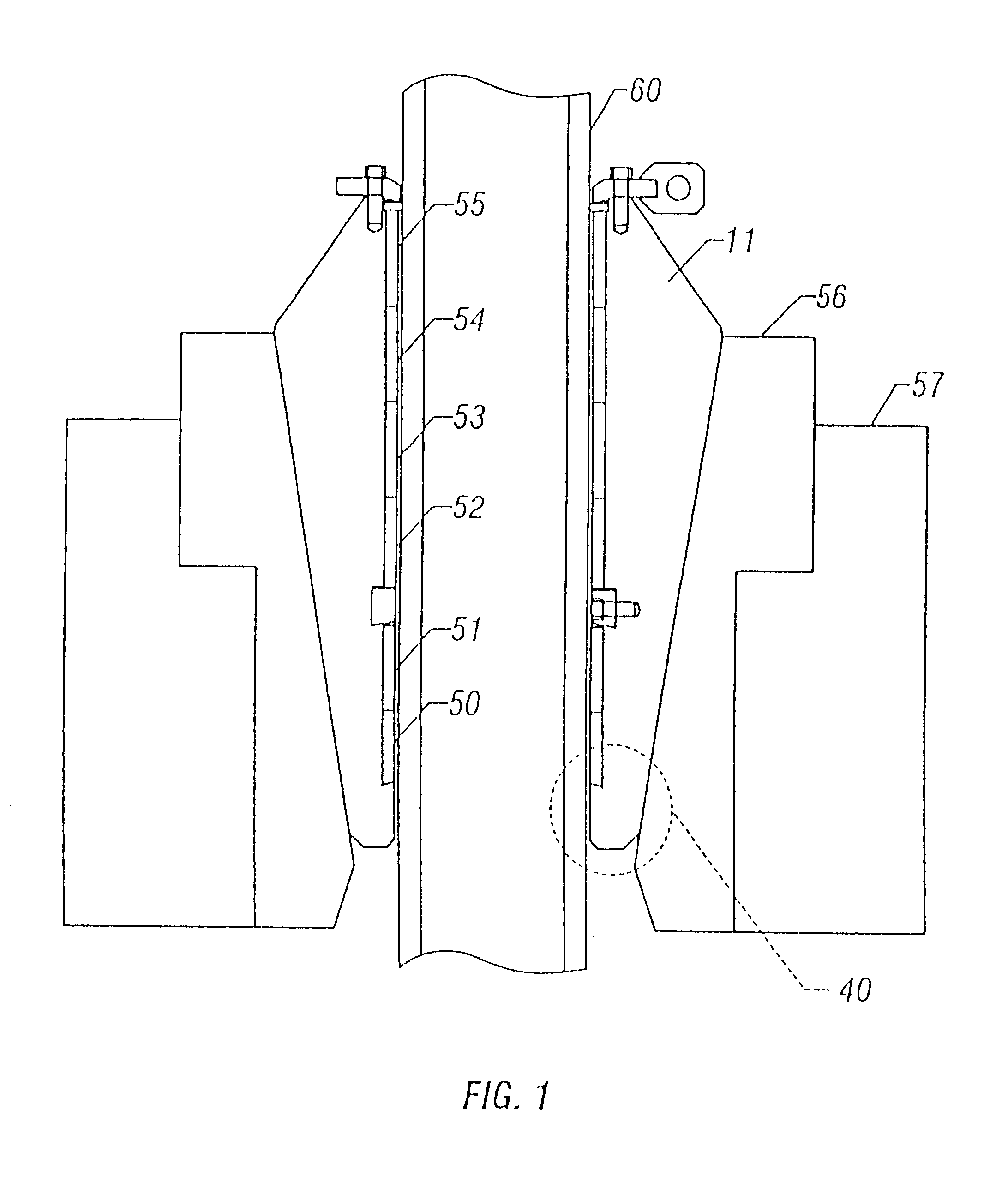
A description of certain embodiments of the present invention is provided to facilitate an understanding of the invention. This description is intended to be illustrative and not limiting of the present invention. A preferred embodiment of the slip assembly of the present invention is described with respect to its use on a drilling rig. However, it is intended that the slip assembly of the present invention can be utilized for any operation where a tubular member is required to be held substantially motionless in a vertical position.

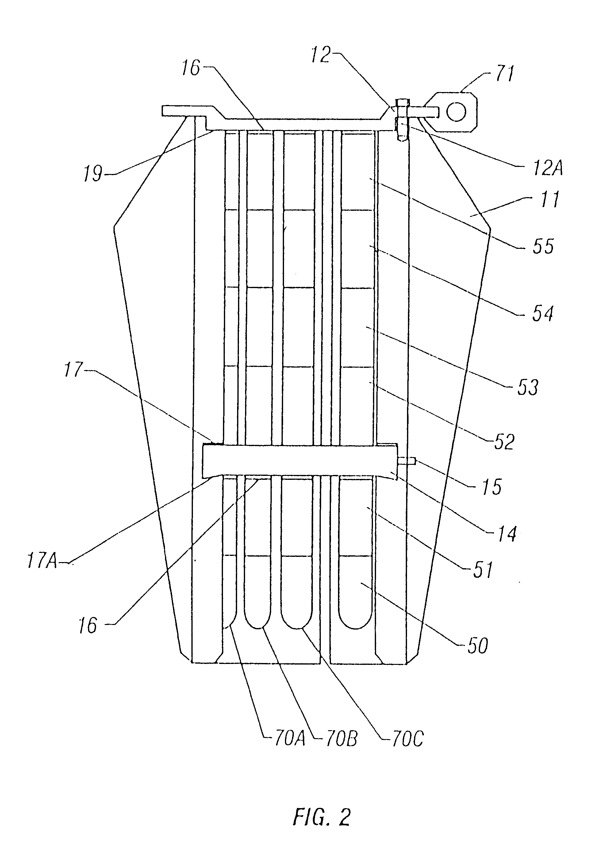
With reference to FIG. 1, apparatus in accordance with the present invention comprises slip bowl 56 which is supported by a rotary table 57. The inner surface of the slip bowl 56 resembles a truncated cone and tapers from a larger diameter at the top to a smaller diameter at the bottom. A slip segment assembly 11 comprises a plurality of slip segments S1, S2, and S3 (see FIG. 8), and the outer surfaces of these slip segments engage the inner surface of b...


PUM


Abstract

The present invention relates to improvements in drill slip assemblies for use in holding a drill pipe or other tubular member in a vertical position above or within a wellbore. The invention comprises a plurality of slip segments assembled in a slip bowl, each segment containing a plurality of dies which grip the tubular member to prevent any axial displacement. The invention provides at least three improvements over prior art drill slips. First, the outer surface of the slip segment assembly, particularly the lower nose region, is fully supported by the inner surface of the slip bowl such that no portion of the slip segment assembly extends below the bowl. Second, the slip segments are fabricated from forged steel, making them more durable and able to carry higher loads. Third, each die in the lowermost set of hardened dies is fabricated having a rounded bottom end with a tapered profile to complement the rounded bottom of the axial grooves cut into each slip segment.

Description

1. Field of the InventionThe present invention generally relates to apparatus for holding pipe or other tubular members in a vertical position, and, particularly, to apparatus which is useful in oilfield operations for drilling, setting casing, or placing or removing any tubular member from a wellbore. The present invention increases the strength of drill pipe slip assemblies.2. Description of the Prior ArtIn the drilling or workover of oil and gas wells, it is necessary to thread together numerous links of tubular goods, or pipe. These tubular members may, for example, comprise either a drill string which rotates a bit at the bottom thereof, or a pipe conduit such as production tubing or well casing which is placed and cemented in the wellbore to prevent its walls from collapsing. In the drilling operation, at least some of the weight of the pipe string extending into the well bore is supported by a traveling block and tackle arrangement from a derrick which extends upwardly from t...

Claims


Application Information

Patent Timeline
Patent Type & Authority Patents(United States)
IPC IPC(8): E21B19/10E21B19/00
CPCE21B19/10Y10T403/7064
Inventor ALLAMON, JERRY P.MILLER, JACK E.
Owner ALLAMON INTEREST
Why Eureka
Try Eureka