
Device for signalling spatial separation or closeness beyond or within a predetermined limit

Inactive Publication Date: 2002-10-29
SORRIAUX PIERRE
View PDF10 Cites 38 Cited by
  • Summary
  • Abstract
  • Description
  • Claims
  • Application Information

AI Technical Summary

Benefits of technology

Transmitting identity information encoded in a form that varies with each frame provides a high level of security not only against attempts at fraud, but also against electromagnetic transmissions in the form of interference or coming from similar apparatuses operating nearby.
The fact that the receiver passes to an inactive state only after a predetermined time interval has elapsed after the alarm has been raised gives the user time to get back close to a monitored article which might have been left behind inadvertently, without deactivating the receiver. The receiver thus remains active without the user needing to perform any maneuver of any kind after the alarm has been raised.
This disposition makes it possible to associate a plurality of monitored units with the same alarm unit, with the alarm unit interrogating the monitored units sequentially by transmitting personalized interrogation signals.

Problems solved by technology

It is not suitable for reliable use in all environments.

Method used


Image

  • Device for signalling spatial separation or closeness beyond or within a predetermined limit
  • Device for signalling spatial separation or closeness beyond or within a predetermined limit
  • Device for signalling spatial separation or closeness beyond or within a predetermined limit

Examples


first embodiment

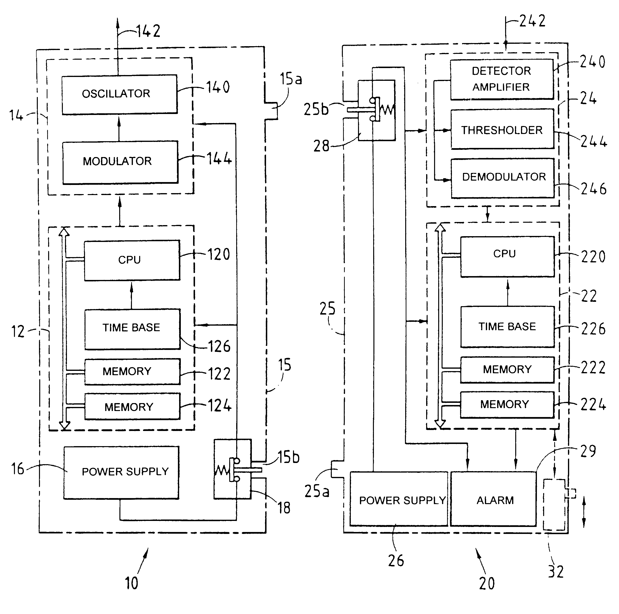
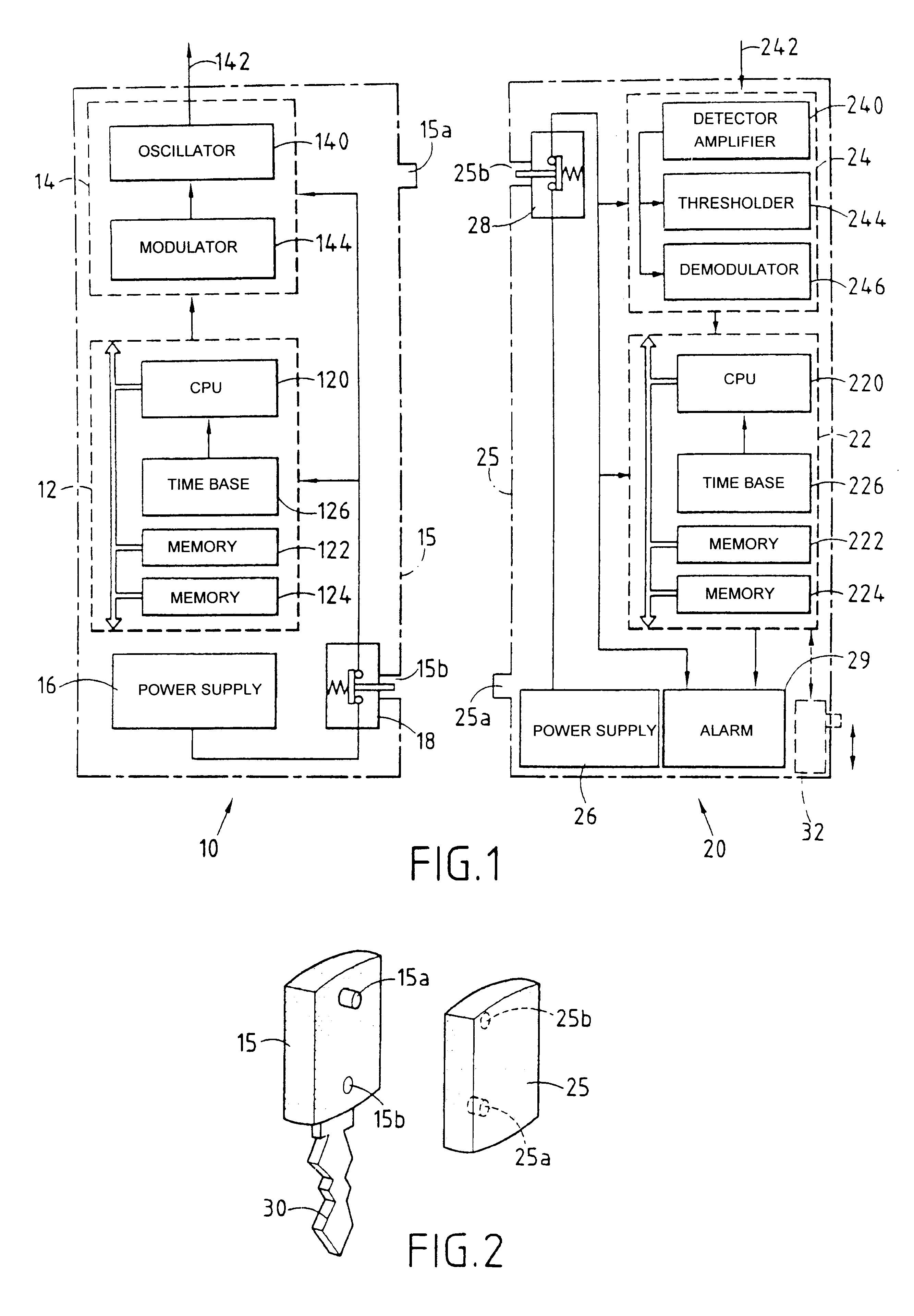
FIG. 1 shows, very diagrammatically, alarm apparatus of the invention comprising a first unit 10 constituting a monitored unit, and a second unit 20 constituting an alarm unit.

The first unit 10 comprises a control circuit 12, a transmitter 14, an electrical power supply 16, and an on / off switch 18.

In conventional manner, the control circuit 12 includes a central unit 120, memories 122, 124, and a time base 126 providing clock signals.

The transmitter 14 comprises an oscillator 140 whose output is connected to an antenna 142, and a modulator 144 controlled by the circuit 12. The oscillator produces a signal at a frequency which can be several hundreds of MHz, for example. The digital signals received from the control circuit 12 in the form of periodic frames are transformed into pulse trains that are applied to the antenna 142. Each frame contains identity information specific to the unit 10.

The second unit 20 comprises a control circuit 22, a receiver 24, and electrical power supply ...

second embodiment

FIG. 4 shows apparatus of the invention. Elements which are common to the embodiments of FIGS. 1 and 4 are given the same references and they are not described again in detail.

The second unit 20 differs from that of FIG. 1 in that it has a transmitter 23 connected to the antenna 242. The transmitter 23 comprises an oscillator 234 and a modulator 236 controlled by the control circuit 22. The transmitter produces a periodic interrogation signal in the form of pulse trains.

The first unit 10 differs from that of FIG. 1 in that it comprises a receiver 13 connected to the antenna 142. The receiver 13 comprises a detector and amplifier circuit 134 and a demodulator 136 connected to the control circuit 12. In response to receiving and detecting the interrogation signal, the control circuit 12 causes the transmitter 14 to operate and transmit one or more frames.

The unit 20 can be associated with a plurality of units 10, 10', 10", . . . which are interrogated in turn by varying the interrogat...


PUM


Abstract

A first unit (10) comprises a first transmitter (12) for wireless transmission of a signal in the from of periodic frames comprising identity information encoded in varying form in each frame, and a second unit (20) comprises a first receiver (22) for receiving said signal and for causing an alarm (29) to operate in response to failure to receive or to recognize identity information. Means (16, 26, 15a, 25a, 15b, 25b) are provided for automatically deactivating at least one of the first and second units when they are physically close together, and for automatically activating said units when they are physically separate from each other.

Description

A particular application of the invention lies in warning a person when that person becomes separated by more than a certain distance from an article, another person, or an animal for which said person is the holder, guardian, or minder. For example, the article can be an item of personal belongings, of baggage, a key, or a bunch of keys, and the purpose of the apparatus of the invention is to warn its holder that the article has been forgotten or that the holder is too far away to oversee it properly.Another application of the invention lies in warning a person when that person or some article, other person, or animal approaches a particular place closer than a certain distance, e.g. corresponding to a safety perimeter.French patent application FR 2 676 135 describes a system that is intended more particularly for indicating that a child has gone further than a predetermined distance from its minder. A transmitter unit carried by the child sends a signal to a fixed station near the...

Claims


Application Information

Patent Timeline
IPC IPC(8): G08B21/24G08B21/00G08B13/14G08B25/00G08B25/10
CPCG08B13/1427G08B21/0227G08B21/0247G08B21/24
Inventor SORRIAUX, PIERRE
Owner SORRIAUX PIERRE
Learn More