Image forming apparatus, transfer belt unit, cleaning device and cleaner unit used for image forming apparatus

a technology of image forming apparatus and cleaning device, which is applied in the direction of electrographic process apparatus, instruments, optics, etc., can solve the problem of inability to contact toner on the intermediate transfer belt, and achieve the effect of reliable removal of waste toner and simple configuration

Inactive Publication Date: 2002-11-05
PANASONIC CORP
View PDF22 Cites 21 Cited by
  • Summary
  • Abstract
  • Description
  • Claims
  • Application Information

AI Technical Summary

Benefits of technology

It is an object of the present invention to provide an image forming apparatus capable of reliably removing waste toner on a toner supporting member of a transfer bel

Problems solved by technology

At this time, a large amount of toners on the intermediate transfer belt are attached to the frictionally c

Method used


Image

  • Image forming apparatus, transfer belt unit, cleaning device and cleaner unit used for image forming apparatus
  • Image forming apparatus, transfer belt unit, cleaning device and cleaner unit used for image forming apparatus
  • Image forming apparatus, transfer belt unit, cleaning device and cleaner unit used for image forming apparatus

Examples


first embodiment

The following is an explanation of a first embodiment of an image forming apparatus according to the present invention, with reference to FIGS. 1 to 5.

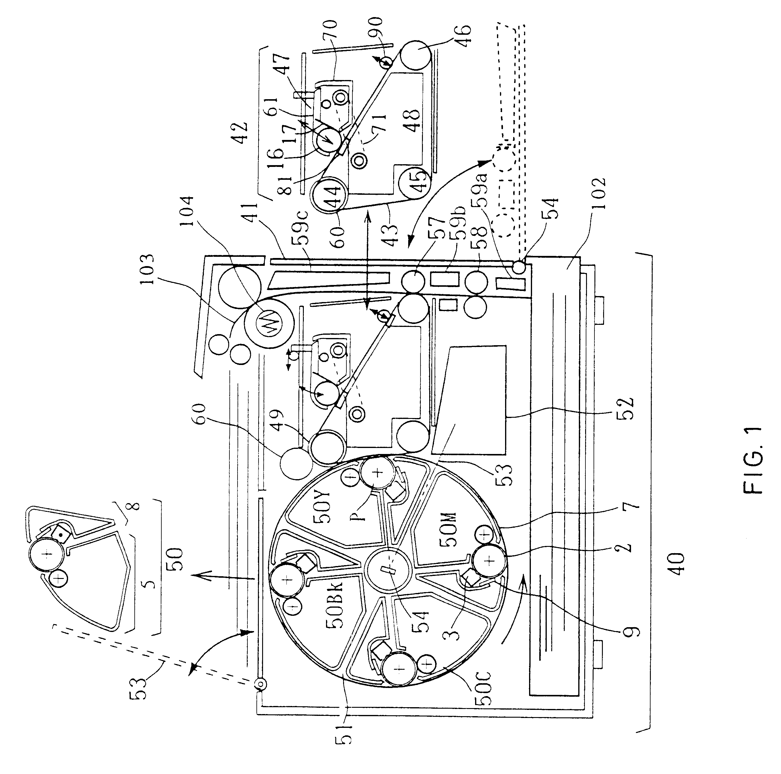
FIG. 1 is a cross-sectional view showing a configuration of an image forming apparatus of a first embodiment according to the present invention. In FIG. 1, the right-hand face is the front face of the color image forming apparatus 40. The front face is provided with a front door 41. Reference numeral 42 is a transfer belt unit for copying (primary transfer) a toner image formed on the photosensitive member 2 at an image forming position (a primary transfer position) P and transferring again (secondary transfer) the copied toner image onto a recording paper. The transfer belt unit 42 includes an intermediate transfer belt 43, three supporting axes including a driving axis 44 for suspending the intermediate transfer belt 43, a tension axis 45 and an opposing axis 46 for the secondary transfer, a cleaner 47 and a waste toner case 48 for ...

second embodiment

The following is an explanation of a second embodiment of an image forming apparatus according to the present invention, with reference to FIGS. 7 and 8.

FIG. 7 is an enlarged view showing a configuration in the vicinity of a press portion of a pretreatment roller of an image forming apparatus in a second embodiment according to the present invention. FIG. 8 is a view showing a configuration of a holder of the pretreatment roller 90.

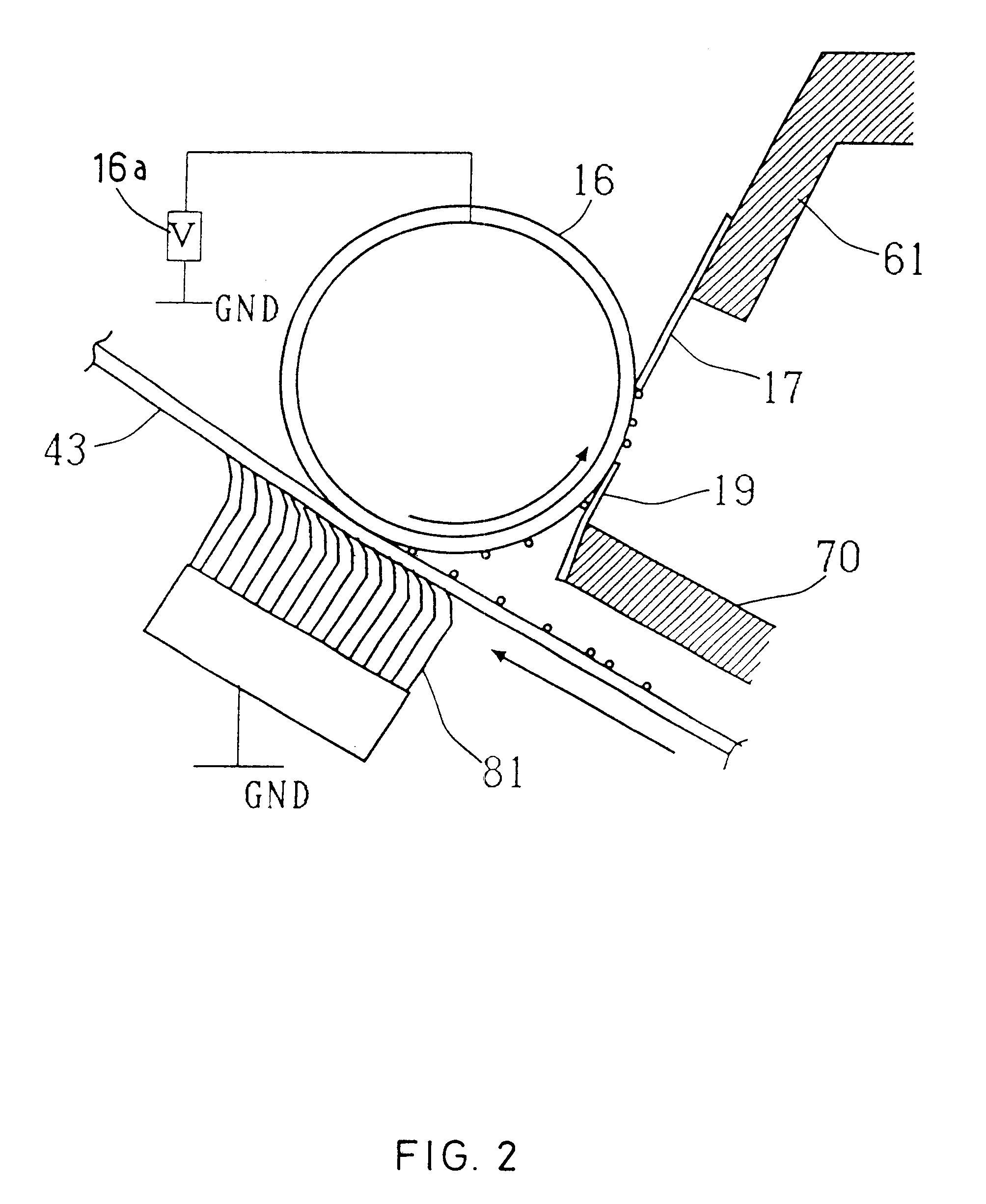
As shown in FIG. 7, in this embodiment, unlike the first embodiment, an opposing brush 110 is provided facing the pretreatment roller 90 while sandwiching the intermediate transfer belt 43 between the opposing brush 110 and the pretreatment roller 90. The opposing brush 110 is made of the same material as that of the opposing brush 81 of the first embodiment. A voltage of +230V is applied to the cleaner roller 16 and electrical conduction between the opposing brush 110 and cleaner 16 is established. When the pretreatment roller 90 is pressed onto to the i...

third embodiment

The following is an explanation of a third embodiment of an image forming apparatus according to the present invention, with reference to FIGS. 9 and 10. FIG. 9 is a view showing a configuration of an image forming apparatus of a third embodiment according to the present invention. FIG. 10 is an enlarged view showing a cleaning portion.

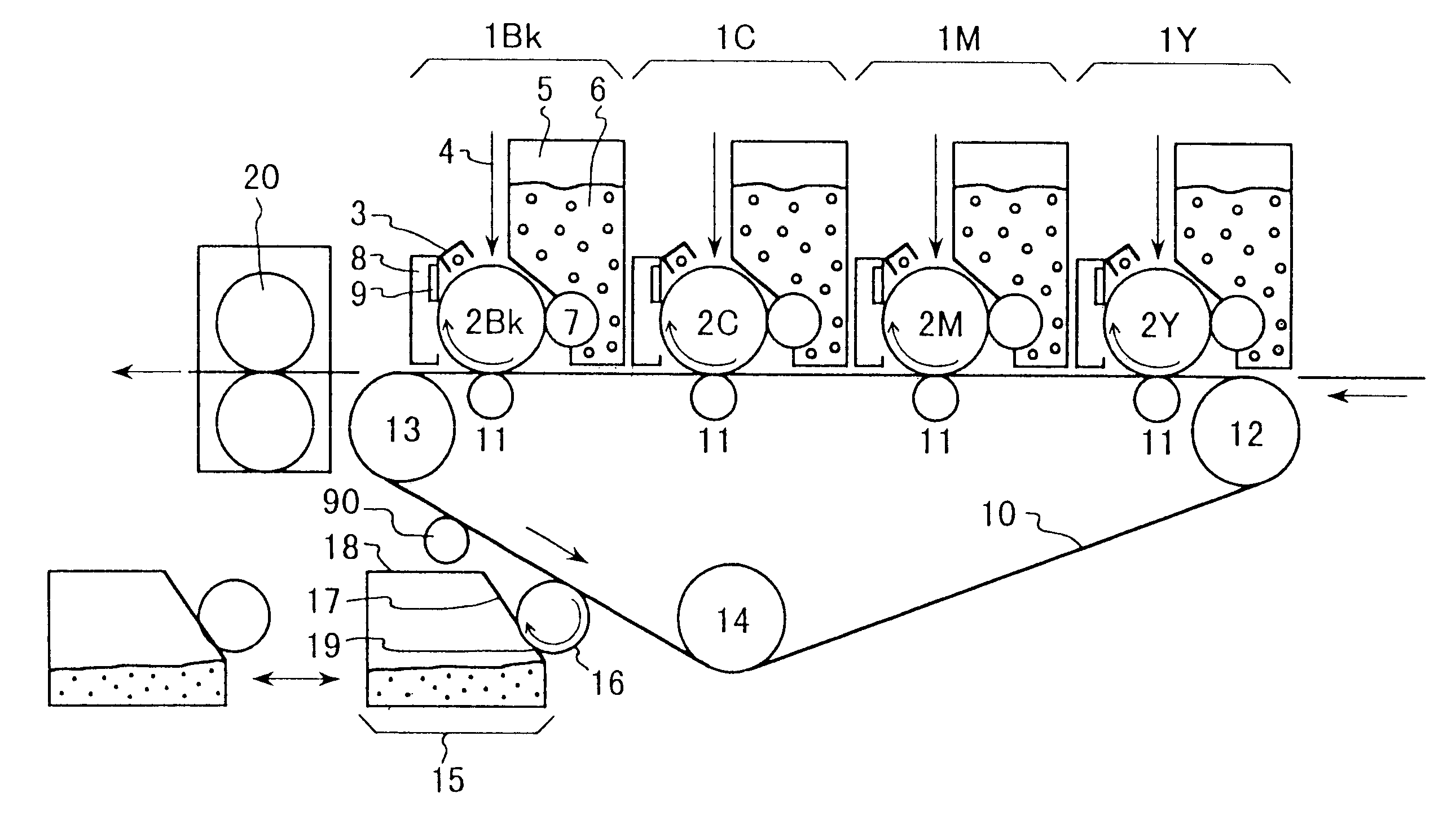
In FIG. 9, reference numeral 1 denotes an image forming unit, integrating the process elements that are arranged around each of the various photosensitive members 2 of the colors yellow (Y), magenta (M), cyan (C), and black (Bk). Each image forming unit is made of the following components. In this configuration, image forming units 1Y, 1M, 1C, and 1Bk for yellow, magenta, cyan, and yellow are arranged from the right side (the side of a paper feeder) to the left side (paper sending portion) in this order. Herein, the photosensitive member 2 is formed in a drum shape having a diameter of 30 mm and rotates at the speed of about 100 mm / sec in the arrow di...


PUM


Abstract

An image forming apparatus capable of removing a toner remaining on the transfer belt (toner supporting member) with a simple configuration. The image forming apparatus includes an intermediate transfer belt that moves with charged toner supported on the surface thereof; a cleaner roller that is rotated while being pressed onto the intermediate transfer belt; a power source for supplying potential for electrically attracting the toner to the cleaner roller from the intermediate transfer belt; and a pretreatment roller that is pressed onto the intermediate transfer belt upstream from the cleaner roller in the moving direction of the intermediate transfer belt.

Description

FIELD OF THE INVENTIONThe present invention relates to monochrome and color image forming apparatus applicable as, for example, a printer, a copying machine, a facsimile, or the like, and to a transfer belt unit, a cleaning device, and a cleaner unit, which are used for the image forming apparatus.BACKGROUND OF THE INVENTIONA conventional image forming apparatus, in particular, an image forming apparatus having a cleaning mechanism for removing toner remaining on a transfer belt is disclosed, for example, in JP 9-80934 A.The image forming apparatus disclosed in the above-mentioned publication includes a charging member for charging waste toner remaining on the transfer belt after secondary transfer, and a collecting member for collecting the waste toner charged by the application of voltage. The apparatus is designed so that the charge of the waste toner on the transfer belt is equalized by applying a voltage to the charging member, and then the waste toner with the equalized charge...

Claims


Application Information

Patent Timeline
IPC IPC(8): G03G15/16G03G21/00
CPCG03G15/161G03G21/0058G03G21/007G03G2215/0116G03G2215/1661G03G2221/0005
Inventor ASAKURA, KENJITAMAI, YASUTAKAYOSHIKAWA, MASANORIKATAKABE, NOBORUOTSUKA, MASAWO
Owner PANASONIC CORP
Why Eureka
Try Eureka