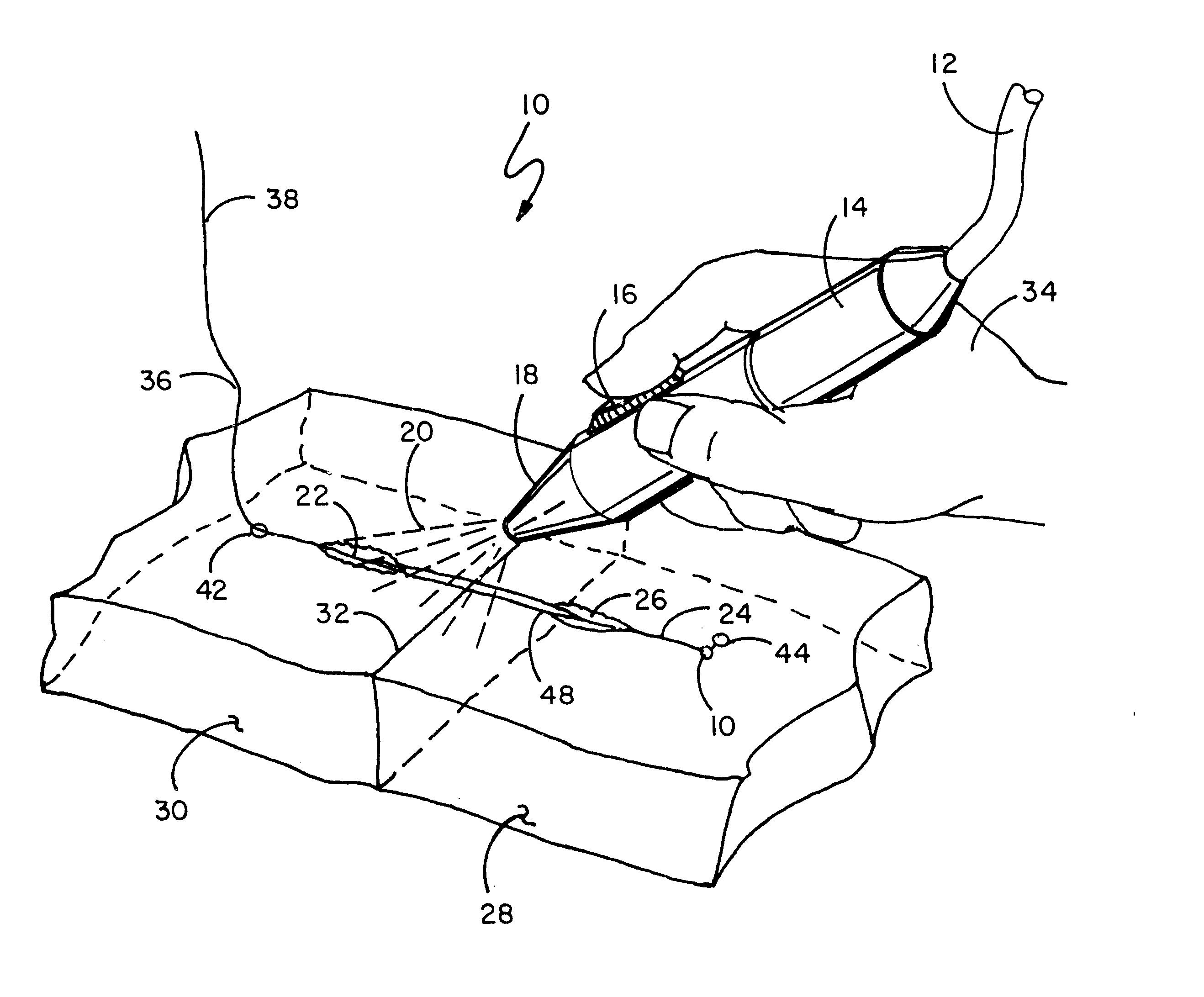
The structure of this invention in one embodiment consists of a suture
assembly having an elongated body member with first and second ends and having a needle member disposed at one end thereof, a stop member at the other end thereof, and adhesive disposed along the body member. In use one would insert the needle member on the surface of the skin at an
entry point adjacent to the cut to be closed on the first side of the cut and draw the suture material, such as a thread member, through the body tissue and out through the first inside of the cut and then into the second inside of the cut and then up through the body tissue of the second side and out an
exit point on the surface of the second side of the cut. One would draw the needle member and attached suture / thread member, pulling the suture carrying the adhesive into the body tissue such that the suture is positioned within both sides of the cut. When used, a stop member prevents pulling the suture too far when the suture is stopped from further movement by the stop member's contact with the surface of the skin. One then pulls the sides of the cut together and then activates the adhesive from the exterior of the skin by applying high-frequency
radiation onto the skin which radiation passes through the skin and activates and sets the adhesive, thereby retaining the body tissue to the suture and holding the sides of the cut together. The end of the thread member can be
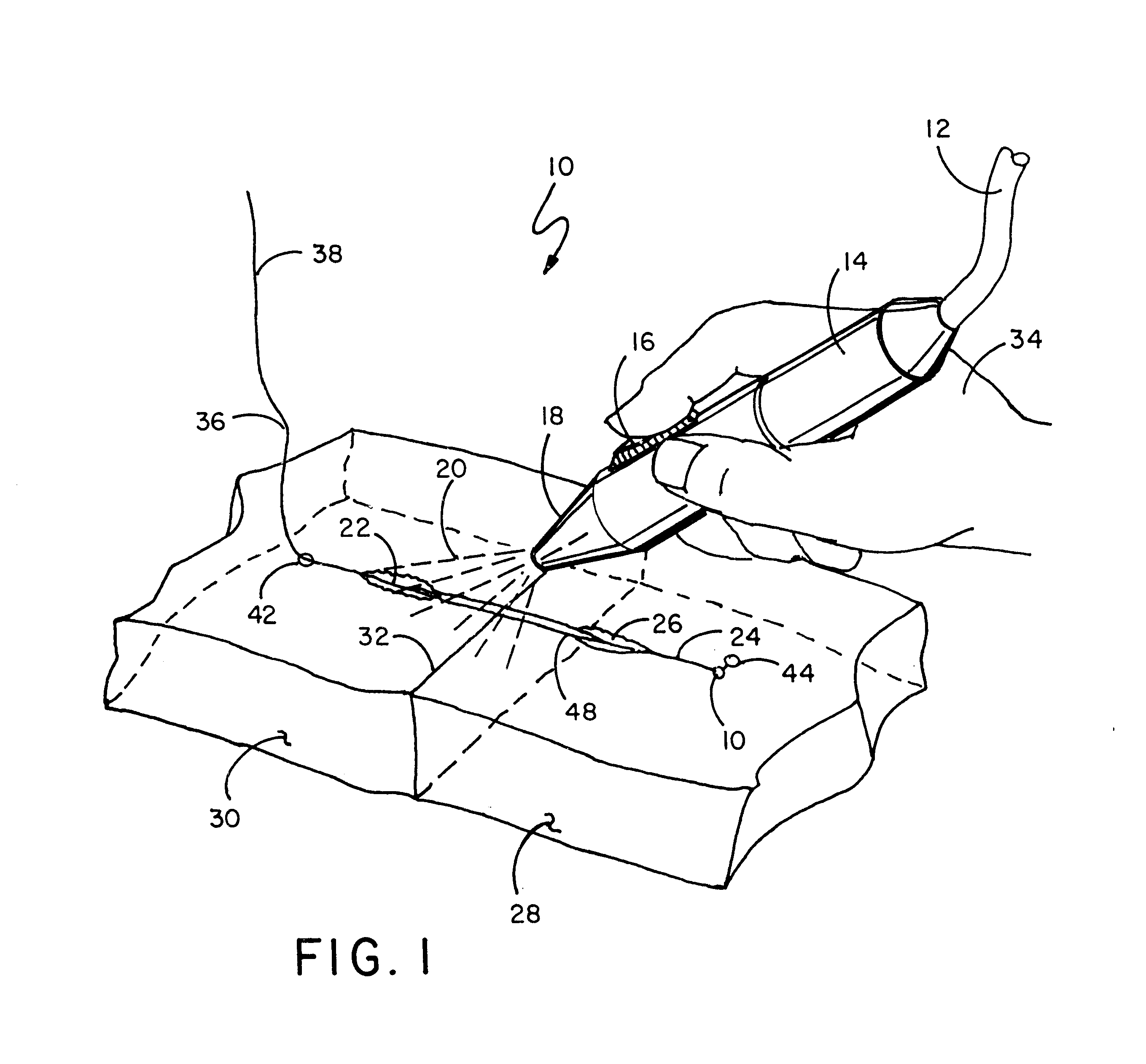
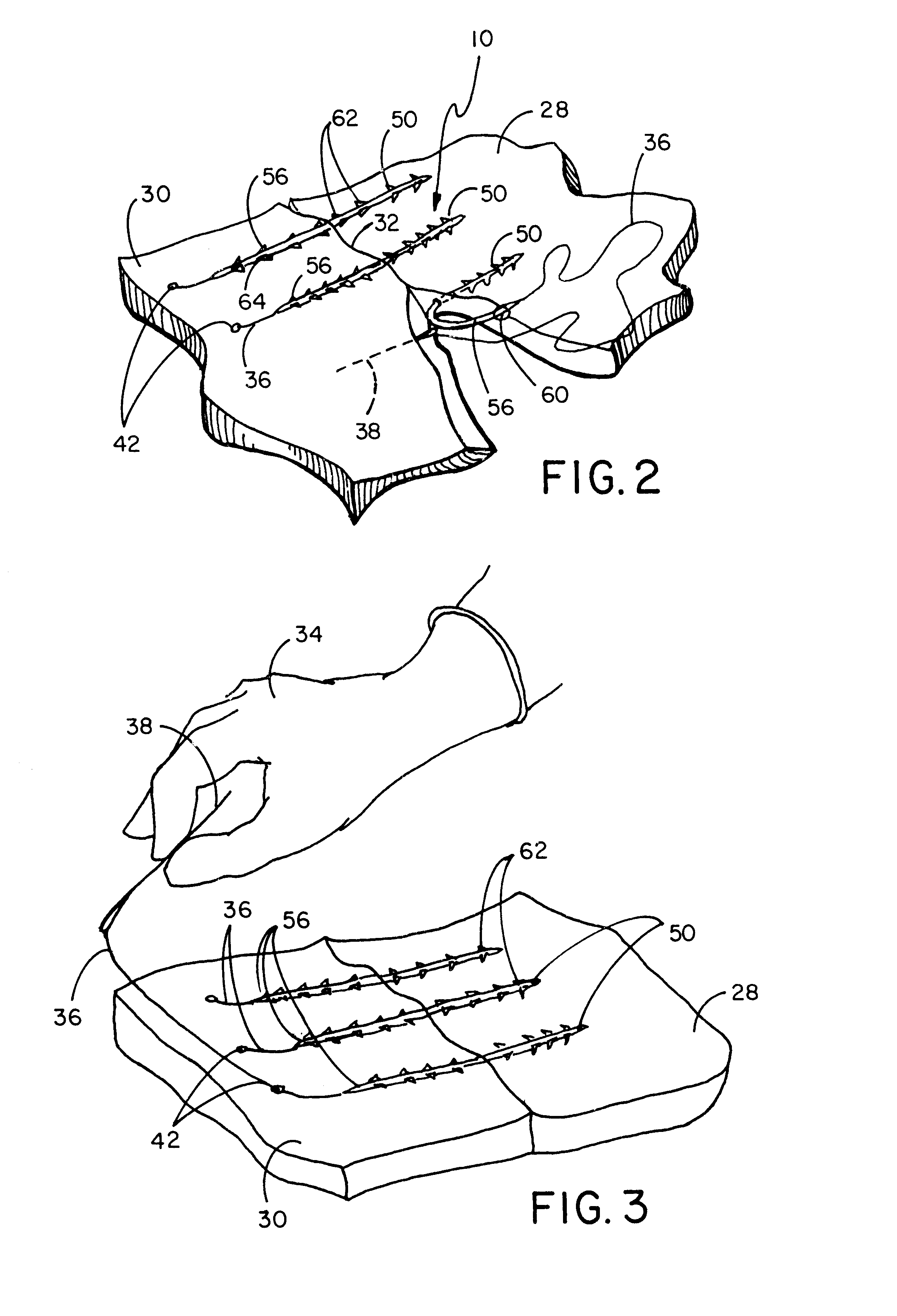
cut off once the suture has brought the two sides of the cut together and the suture has been fixed in position by application of high-frequency radiation to set the adhesive. Other types of single sutures can be used such as a suture having a rigid portion for
insertion into one side of the cut and a flexible portion which is easily manipulable and pulled by the needle and thread into the other side of the cut after which the cut is closed around the suture and the adhesive on the suture is externally activated, as described above. In some embodiments the suture can include barbs, as described in my prior art inventions, to aid in retaining the body tissue therearound as the suture is positioned for the adhesive to be externally activated. Such improved
fastener and joining method can also be used for the fixation of internal tissues such as knee
lateral displacement corrections,
ligament reattachment operations and the like where an externally activatable and curable adhesive
coating on such suture can act as a procedural aid to temporarily hold tissues in tension while the surgeon is performing other acts. The use of the suture of this invention can also be helpful in dental and facial
surgery as it eliminates annoying suture knots.
It should be noted that an adhesive can be utilized which, when one frequency of high-frequency radiation is externally applied, will be activated and cured; and when a different frequency radiation is applied to the cured adhesive, will be deactivated, turning the adhesive to a
liquid state so that the suture is released from its hold in the tissue. Such liquid adhesive is absorbed by the body. This activation and deactivation of the adhesive is particularly well suited when using temporary suturing as it allows for the reopening of an incision when further work is needed to be done.

