
Plant for generating electric power and a method for operation of such a plant

a technology for generating electric power and electric power plants, applied in the direction of electric generator control, machines/engines, mechanical equipment, etc., can solve the problem of insufficient precision in the method

Inactive Publication Date: 2002-11-12
ABB POWER GRIDS SWITZERLAND AG
View PDF11 Cites 60 Cited by
  • Summary
  • Abstract
  • Description
  • Claims
  • Application Information

AI Technical Summary

Benefits of technology

According to another preferred embodiment of the invention said members of the arrangement are adapted to send orders to the unit to change the frequency of the alternating voltage in a first direction, in an increasing or decreasing direction, and if the power measured by said means then increases send orders to continue the change of the frequency in said first direction, and if the power from a measurement carried out by said means decreases to the measurement following thereupon change the direction into an opposite second direction for the change of the frequency of the alternating voltage. The power maximum asked for may in this way be reliably determined. It may then be advantageous that the intervals of the changes of the frequencies between two subsequent measurements is made finer when a power maximum has been passed, i.e. when suddenly the power delivered decreases again. The regulation may be carried out intermittently, preferably at uniform time intervals, or it may proceed continuously for ensuring that the plant all the time operates at the maximum power that may be delivered.
According to another preferred embodiment of the invention the plant also comprises members adapted to detect the wind velocity close to at least one of the wind power generators and that said members of the arrangement are adapted to elaborate a start-control order for the control of the converter by the unit on the basis of the wind velocity detected corresponding to an optimum frequency of the alternating voltage calculated on the basis of the wind velocity. An arrival to the frequency lying close to said optimum frequency when starting the operation of a plant after an operation interruption, various disturbances of the regulation or the like, may be rapidly obtained by proceeding in this way, so that no power will be unnecessarily lost.
According to another preferred embodiment of the invention said means comprise members for measuring the current intensity and members for measuring the voltage on the alternating voltage line and members for calculating the power fed towards the converter from the. result of these measurements. This constitutes a way to achieve the power measurement according to the invention, which may be realized easily and thereby will be reliable and favourable from the cost point of view.

Problems solved by technology

However, it has turned out that this method is not as precise as desired, since such an average wind velocity is sometimes a too coarse measure of the optimum frequency with respect to the output power delivered.

Method used


Image

  • Plant for generating electric power and a method for operation of such a plant
  • Plant for generating electric power and a method for operation of such a plant
  • Plant for generating electric power and a method for operation of such a plant

Examples


Embodiment Construction

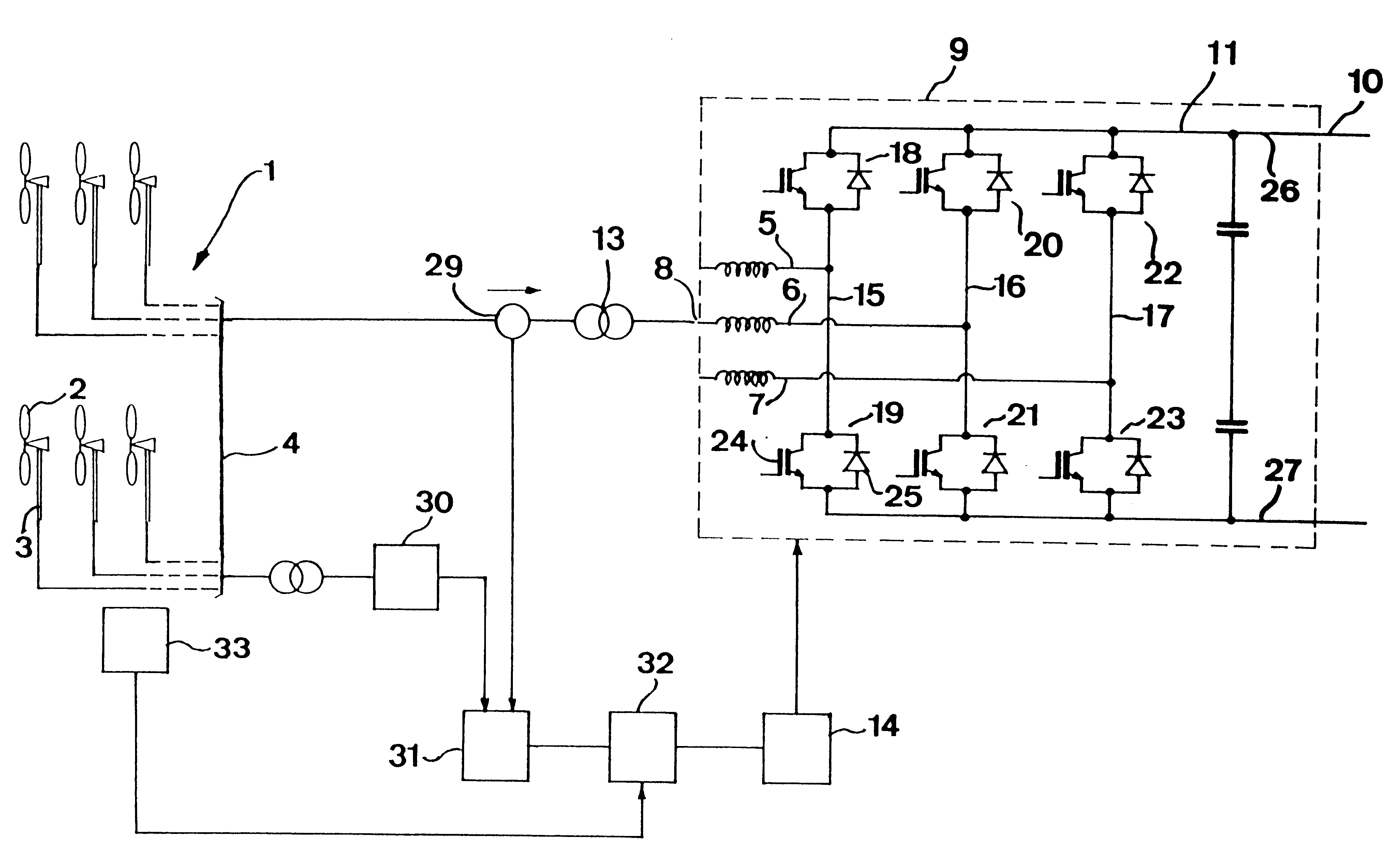
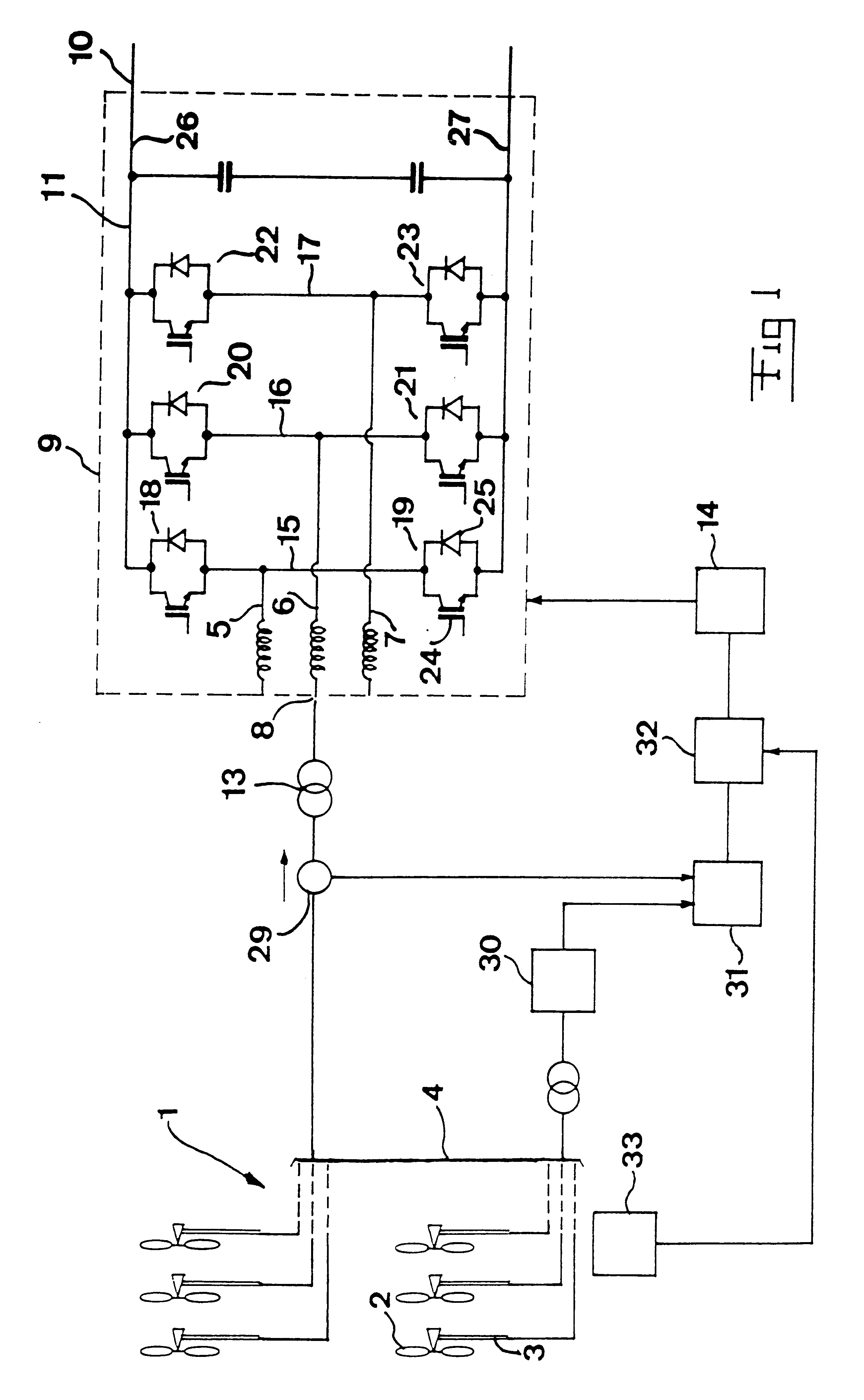
The principle structure of a plant for generating electric power according to a first preferred embodiment of the invention is very schematically illustrated in FIG. 1. The plant has a wind power park 1 having wind power generators 3 separately driven by wind power and schematically indicate through their propellers 2. This wind power park may in practice be formed by a very high number of such so called wind power generators or plants, which may be distributed over a not neglectible land and / or water region. These may for example be positioned according to a 24.times.6 matrice pattern with a distance of for instance 300 meters between each short line and 500 meters between each long line. It is understandable that in such cases the local wind velocities existing at the different wind power generators between the park may differ quite a lot.

The wind power generators are connected to a line 4 in common, to which they deliver an alternating voltage having a certain frequency f. A thre...


PUM


Abstract

In a plant for generating electric power through at least two generators separately driven by wind power and feeding an alternating voltage to an alternating voltage line in common, a converter is adapted to convert the alternating voltage into direct voltage and conversely. The plant has means (29, 30) adapted to measure the total power fed towards the converter from the wind power generators and members (32) adapted to send orders to a unit (14) adapted to control the converter (9) for adjusting the control thereof depending upon power values delivered by said means to such a frequency that a power maximum is obtained.

Description

FIELD OF THE INVENTION AND PRIOR ARTThe present invention relates to a plant for generating electric power comprising at least two generators separately driven by wind power and adapted to feed an alternating voltage to an alternating voltage line in common, a converter adapted to convert alternating voltage into direct voltage and conversely connected with its alternating voltage side to said alternating voltage line, a unit adapted to control the switchings of power semiconductor devices included in a converter and thereby the frequency of the alternating voltage on the alternating voltage line from the generators and an arrangement adapted to determine optimum frequency of the voltage on the alternating voltage line for the wind conditions prevailing, with respect to the maximum power that may be generated by the plant, and send orders to the unit to control the converter for obtaining this frequency of said alternating voltage, as well as a method for operation of such a plant a...

Claims


Application Information

Patent Timeline
Patent Type & Authority Patents(United States)
IPC IPC(8): F03D9/00H02J3/38
CPCF03D9/002F03D9/003H02J3/386F05B2240/96Y02E10/721Y02E10/725Y02E10/763F03D9/25F03D9/255F03D9/257H02J2300/28H02J3/381Y02E10/72Y02E10/76H02J3/46
Inventor ERIKSSON, KJELLWIK, SUNE
Owner ABB POWER GRIDS SWITZERLAND AG
Features
  • Generate Ideas
  • Intellectual Property
  • Life Sciences
  • Materials
  • Tech Scout
  • Unparalleled Data Quality
  • Higher Quality Content
  • 60% Fewer Hallucinations
Learn More