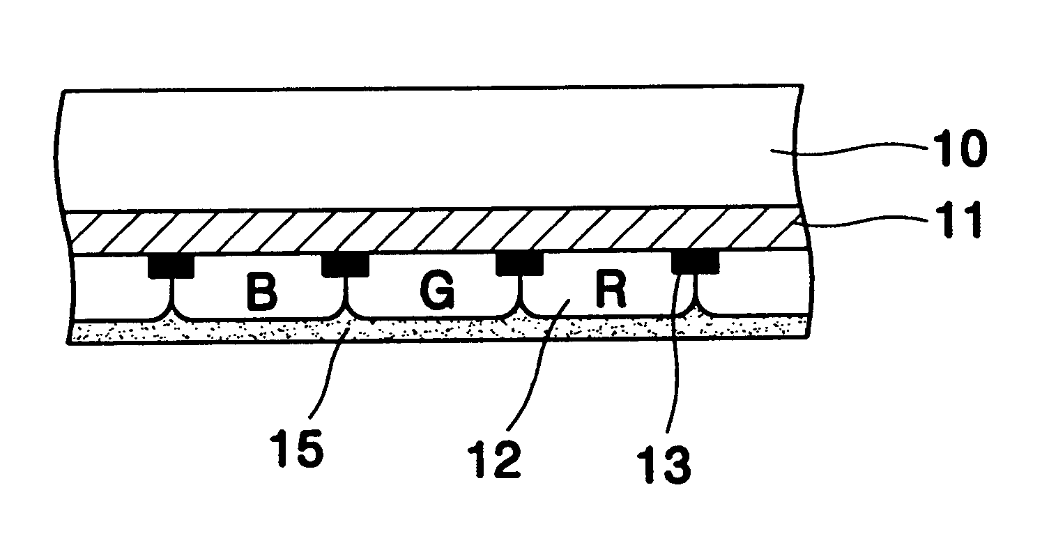
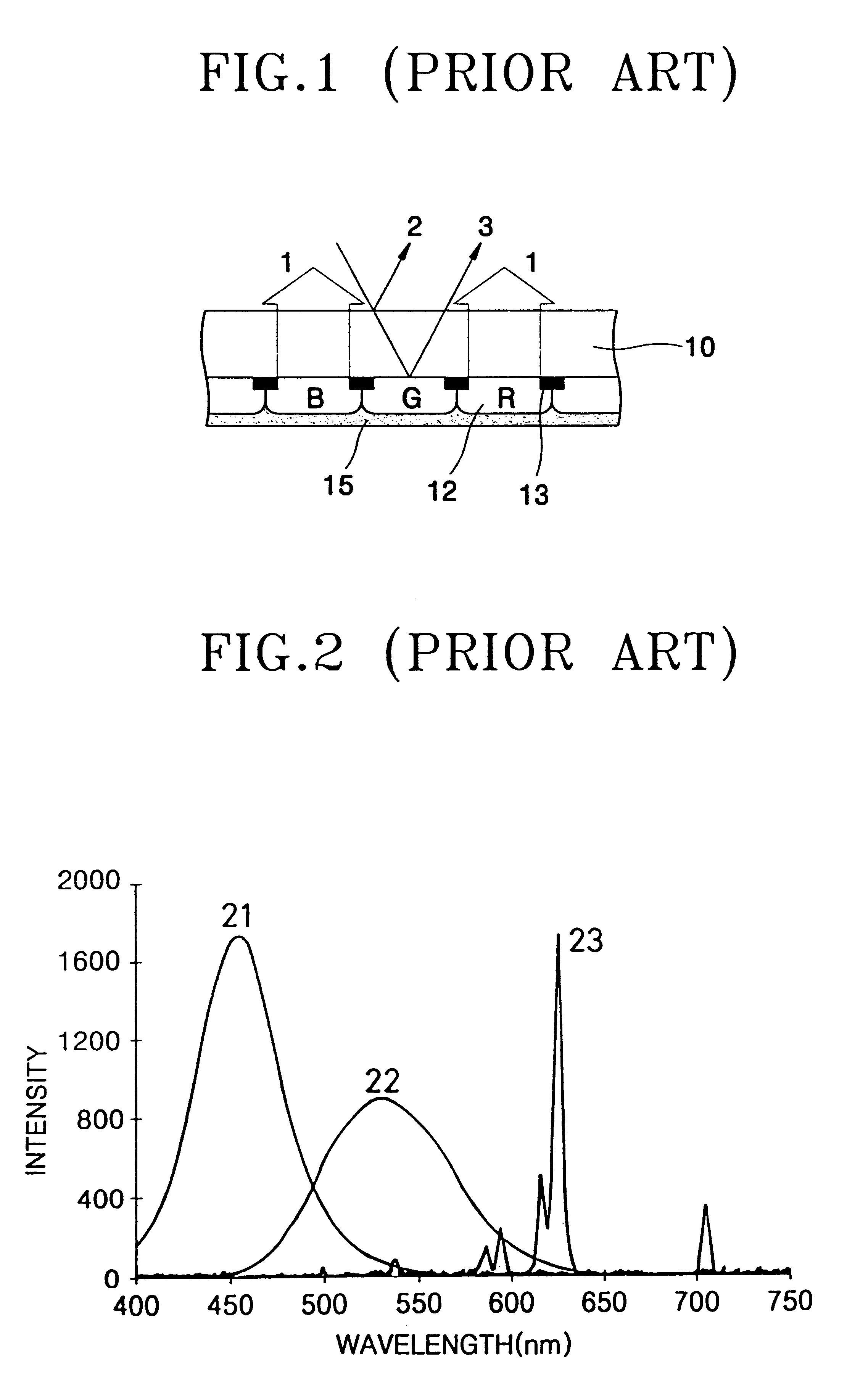
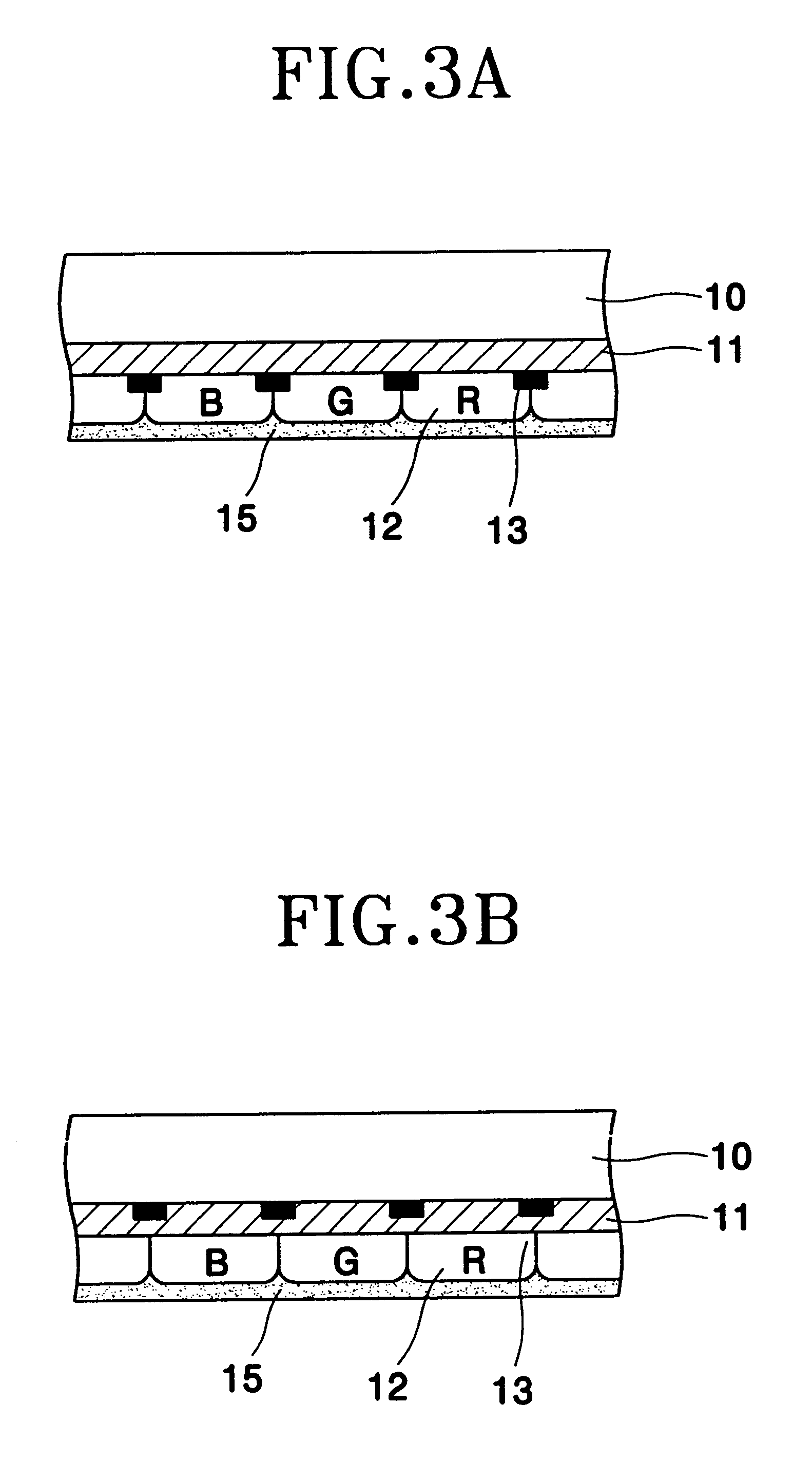
Cathode ray tube

a technology phosphor layer, which is applied in the field of cathode ray tube, can solve the problems of patents that fail to reduce the light reflected off at the phosphor layer, and achieve the effect of reducing the ambient light reflection

Inactive Publication Date: 2002-11-12
SAMSUNG ELECTRONICS DEVICES CO LTD
View PDF15 Cites 7 Cited by
  • Summary
  • Abstract
  • Description
  • Claims
  • Application Information

AI Technical Summary

Benefits of technology

An objective of the present invention is to minimize the ambient light reflection without u

Problems solved by technology

However, these patents fail to reduce li

Method used


Image

  • Cathode ray tube
  • Cathode ray tube
  • Cathode ray tube

Examples


example 1

4.5 g of tetraethyl-ortho-silicate (TEOS) was dispersed in a solvent consisting of 30 g of reagent methanol, 30 g of ethanol, 12 g of n-buthanol and 4 g of de-ionized water. 5 g of HAuCl.sub.4 4H.sub.2 O was added to thus dispersed solvent and stirred at the room temperature for 24 hours to prepare a solution A.

36 g of ethanol, 1.8 g of pure water, 2.5 g of acid (35% density) were added to 25 g of titanium iso-propoxide (TIP) and the mixture was stirred at the room temperature for 24 hours to prepare a solution B.

A coating material was prepared by mixing 12 g of solution A, 3 g of solution B, and 12 g of ethanol so that the content of gold was 12-mol % and the mol ratio of titania and silica was 1:1.

Black matrix was formed on a 17-inch CRT face panel, and 50 ml of the coating material was spin-coated on the panel spinning at 150 rpm. The coated panel was heated at 450.degree. C. for 30 minutes. Next, phosphor layer was formed on the panel in a conventional way.

The thus-made panel ha...

example 2

HAuCl.sub.4 was replaced by NaAuCl.sub.3 with other things being equal to those of Example 1.

example 3

HAuCl.sub.4 was replaced by AuCl.sub.3 with other things being equal to those of Example 1.


PUM


Abstract

A CRT has an improved contrast with a provision of a filter layer where nano-sized metal particles are dispersed in a dielectric matrix to selectively absorb light in predetermined wavelengths, specifically wavelengths between peak wavelengths of primary colors emitted by phosphors coated on the inner surface of the face plate. The improved contrast is a result of the metal particles in a dielectric matrix resonating with particular wavelengths and thus absorbing them.

Description

The present invention is related to a CRT and, more particularly, to its face plate having a light absorbing filter layer having a predetermined absorption peak / peaks.FIG. 1 shows a partial cross-section of the face plate with a phosphor layer coated of a conventional CRT. There are two sources of visible light coming out of the face panel. One is a light 1 emitted from phosphors when electron beams impinge on them. The other is external ambient light reflected from the face panel. The reflected light has in turn two components depending on where the incident external light is reflected. The first component is that reflected on the surface of the face panel. The other is that passes the whole thickness of the face panel but is reflected off at the phosphor surface. The ambient light reflected from the face plate has a uniform spectrum, degrading contrast of a CRT since the CRT is designed to emit light at only predetermined wavelengths and to display a color image by a selective com...

Claims


Application Information

Patent Timeline
IPC IPC(8): H01J29/89H01J9/227H01J9/20H01J29/32H01J29/88
CPCH01J29/898H01J29/10H01J9/20
Inventor LEE, JONG-HYUKPARK, JUNG-HWANCHO, YOON-HYUNGLEE, HAE-SEUNGZANG, DONG-SIK
Owner SAMSUNG ELECTRONICS DEVICES CO LTD
Why Eureka
Try Eureka