Rubber cylinder sleeve, especially for web-fed rotary offset printing machines

a cylinder and cylinder technology, applied in the field of rubber sleeves, can solve the problems of high production cost, high production cost, and the need for continuous middle and lower layers of the same, and achieve the effect of reducing production costs, reducing production costs, and improving production efficiency

Inactive Publication Date: 2002-11-26
MANROLANAD AG
View PDF14 Cites 30 Cited by
  • Summary
  • Abstract
  • Description
  • Claims
  • Application Information

AI Technical Summary

Benefits of technology

The object is achieved by designing the covering layer as a finite layer having a joint location which is filled with a compressible material. The rubber cylinder sleeve can be produced cost-effectively. In addition, it makes possible good printing quality since the joint location filled with compressible material is permitted to dissipate tangential forces during rolling contact with other printing-unit cylinders.

Problems solved by technology

One disadvantage of these known rubber cylinder sleeves (transfer cylinder sleeves) is that the middle and lower layers of the same have to be at least partly continuous.
This has a particularly detrimental effect on the production costs.
Apart from the higher production costs already mentioned, a continuous outer layer has the disadvantage that, during rolling contact with a plate cylinder and an impression cylinder, the rubber blanket sleeve is loaded with tangential forces to which further forces are added with each revolution.
This loading also has a detrimental effect on the printing quality (for example by a tendency to slippage of the rubber blanket sleeve in relation to the web to be printed. in the press nip, and in the rolling nip with a plate cylinder).

Method used


Image

  • Rubber cylinder sleeve, especially for web-fed rotary offset printing machines
  • Rubber cylinder sleeve, especially for web-fed rotary offset printing machines
  • Rubber cylinder sleeve, especially for web-fed rotary offset printing machines

Examples


Embodiment Construction

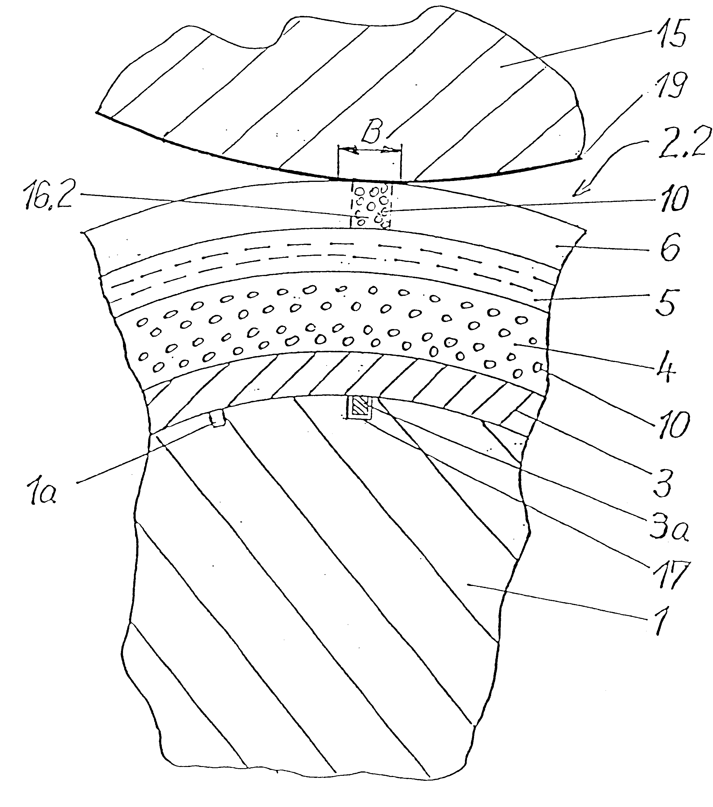
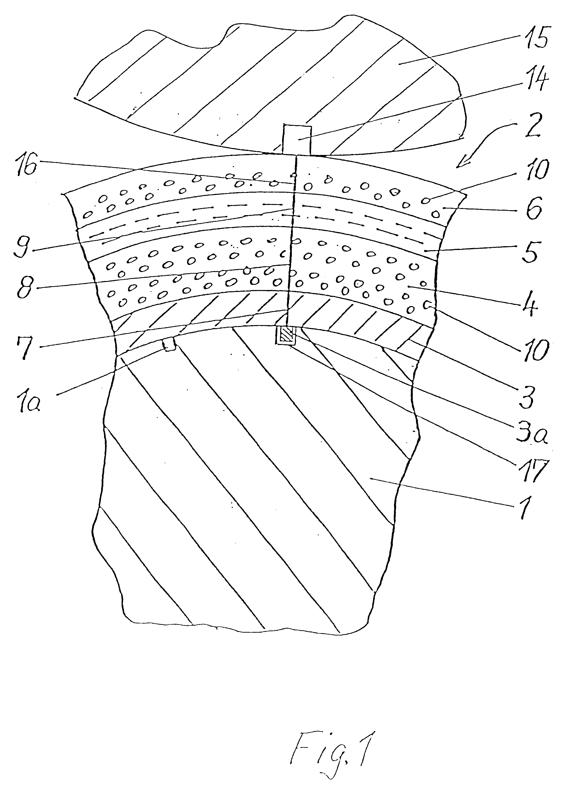
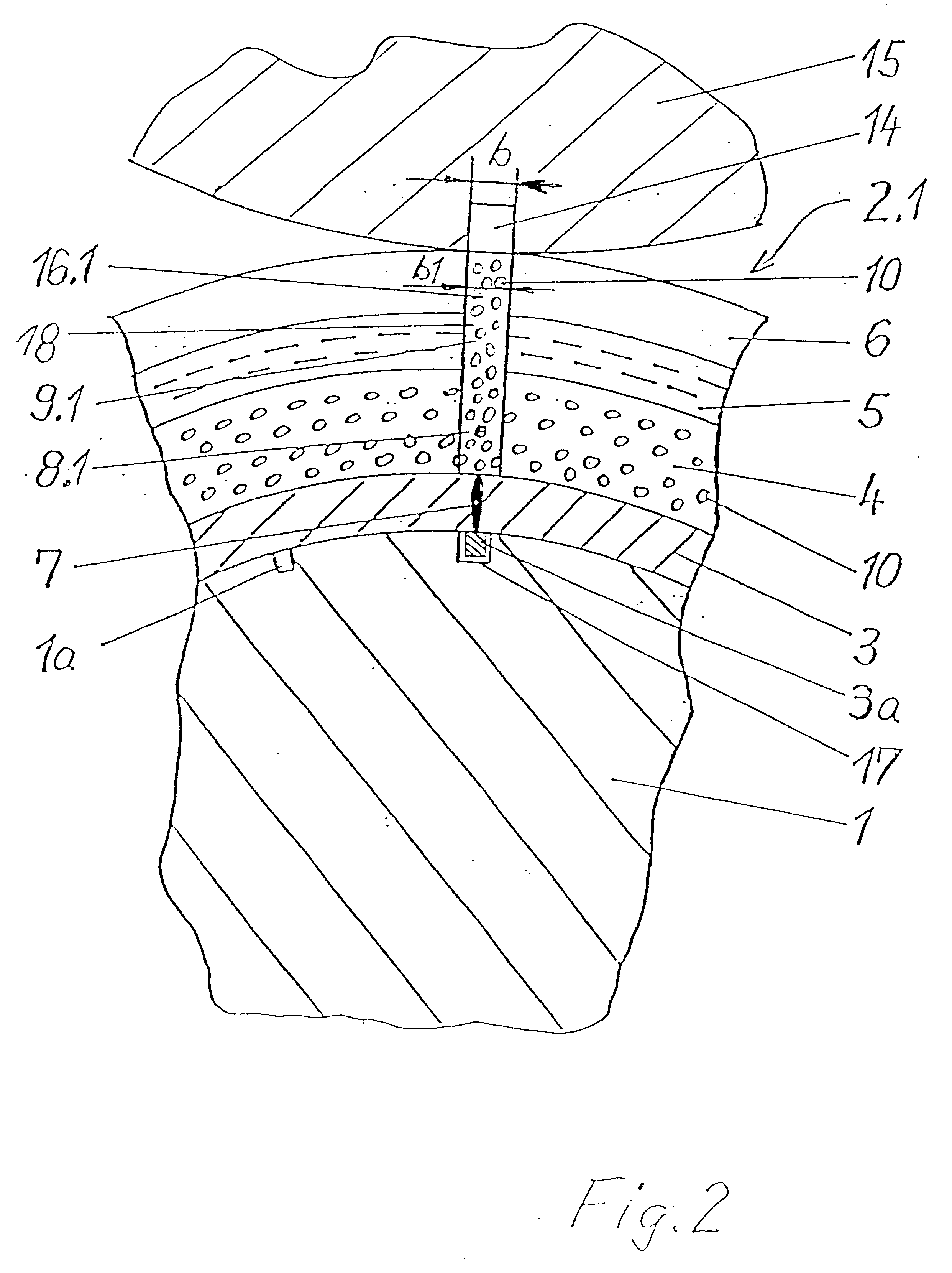
In FIG. 1, the transfer cylinder 1 (rubber blanket cylinder) has openings or nozzles 1a provided at its surface. The transfer cylinder sleeve 2 (rubber blanket sleeve) applied in the above-described manner has, as was explained previously, a metal sleeve 3 which can preferably be expanded by means of air and on which a compressible layer 4 is vulcanized or adhesively bonded. Provided on the compressible layer 4 is a layer of a non-expandable material 5, preferably a hard elastomer layer with short fibres, which are not specifically designated. Provided on the non-expandable layer 5 is a covering layer 6, for example one made of a resilient material, with which printing can be carried out by the offset printing process.

According to the invention, the carrier sleeve 3 used is preferably a metal sleeve, for example one of steel, which can be expanded by means of air and which has a joint location 7. This joint location 7 can be a welded seam which is preferably formed by welding togeth...


PUM


Abstract

A rubber cylinder sleeve for web-fed rotary offset printing machines has a covering layer which is a finite layer having a joint location, the joint location being filled with a compressible material.

Description

1. Field of the InventionThe invention relates to a rubber sleeve having an inner carrier sleeve which can be expanded by means of air, at least one compressible layer arranged over the carrier sleeve, and an outer covering layer. A similar device is disclosed in U.S. Pat. No. 6,148,725.2. Description of the Related ArtSleeves of this type are disclosed, for example, by U.S. Pat. Nos. 5,429,048, 5,323,702, 5,440,981 and 5,304,267. One disadvantage of these known rubber cylinder sleeves (transfer cylinder sleeves) is that the middle and lower layers of the same have to be at least partly continuous. This has a particularly detrimental effect on the production costs.In addition, U.S. Pat. No. 5,351,615 discloses the practice of applying a rubber blanket to a carrier plate, for example by adhesive bonding. After this, this arrangement is shaped into a rubber cylinder sleeve and the mutually facing ends of the carrier plate and those of the rubber blanket or rubber covering are joined t...

Claims


Application Information

Patent Timeline
Patent Type & Authority Patents(United States)
IPC IPC(8): B41N10/00B41N10/04B41N10/06B41N10/02B41F30/02
CPCB41N6/00B41N10/04B41N10/06B41N10/02B41N2210/02
Inventor HOFFMANN, EDUARDKNAUER, PETER
Owner MANROLANAD AG
Why Eureka
Try Eureka