
Image acquisition by push-broom scanning

a pushbroom and scanning technology, applied in the field of image acquisition by pushbroom scanning, can solve the problems of insatiable solutions to mitigate the drawback, the image ceases to be acceptable, and the effect of reducing noise and limited spectrum folding

Inactive Publication Date: 2002-12-10
CENT NAT DETUD SPATIALES C N E S
View PDF6 Cites 19 Cited by
  • Summary
  • Abstract
  • Description
  • Claims
  • Application Information

AI Technical Summary

Benefits of technology

Another solution consists in controlling the attitude of the satellite so as to slow down its rate of scanning. That technique allows light flux to be integrated for longer, but it implies a loss of continuity in the track of the satellite, and consequently leads to a loss of data.
An object of the invention is thus to provide an acquisition method of this type in which instrument noise is reduced and which does not suffer from the drawbacks of the above-mentioned solutions.
To mitigate that drawback, proposals have recently been made, in particular in French patent FR 2 678 460 in the name of the Applicant, to use a technique whereby two offset strips make it possible to perform oversampling so as to limit spectrum folding.
The invention proposes an instrumental solution which makes it possible to obtain images in which firstly spectrum folding is limited and secondly noise is minimized.

Problems solved by technology

It is known that the finer the resolution of an image, the more the signal-to-noise (SNR) tends to diminish, in particular because of the lack of light flux, so that images cease to be acceptable.
Unfortunately, presently known solutions for mitigating that drawback are not satisfactory.
However that solution is expensive.
That technique allows light flux to be integrated for longer, but it implies a loss of continuity in the track of the satellite, and consequently leads to a loss of data.

Method used


Image

  • Image acquisition by push-broom scanning
  • Image acquisition by push-broom scanning
  • Image acquisition by push-broom scanning

Examples


Embodiment Construction

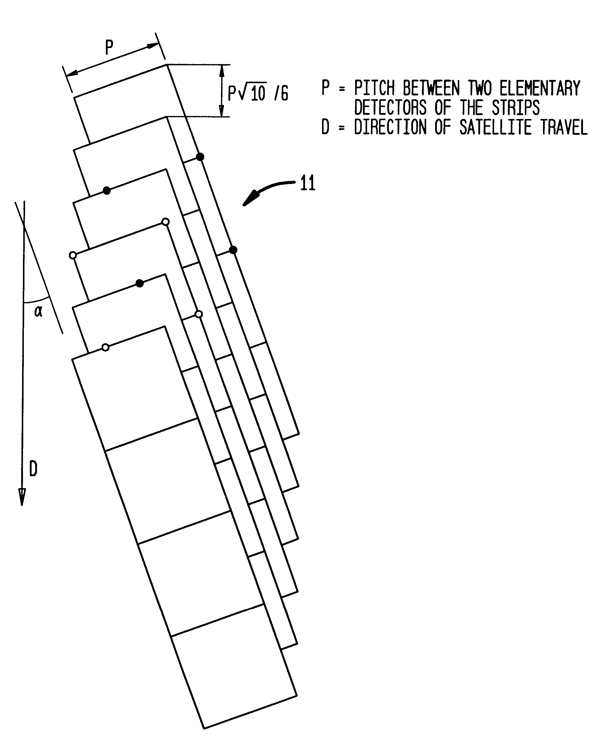
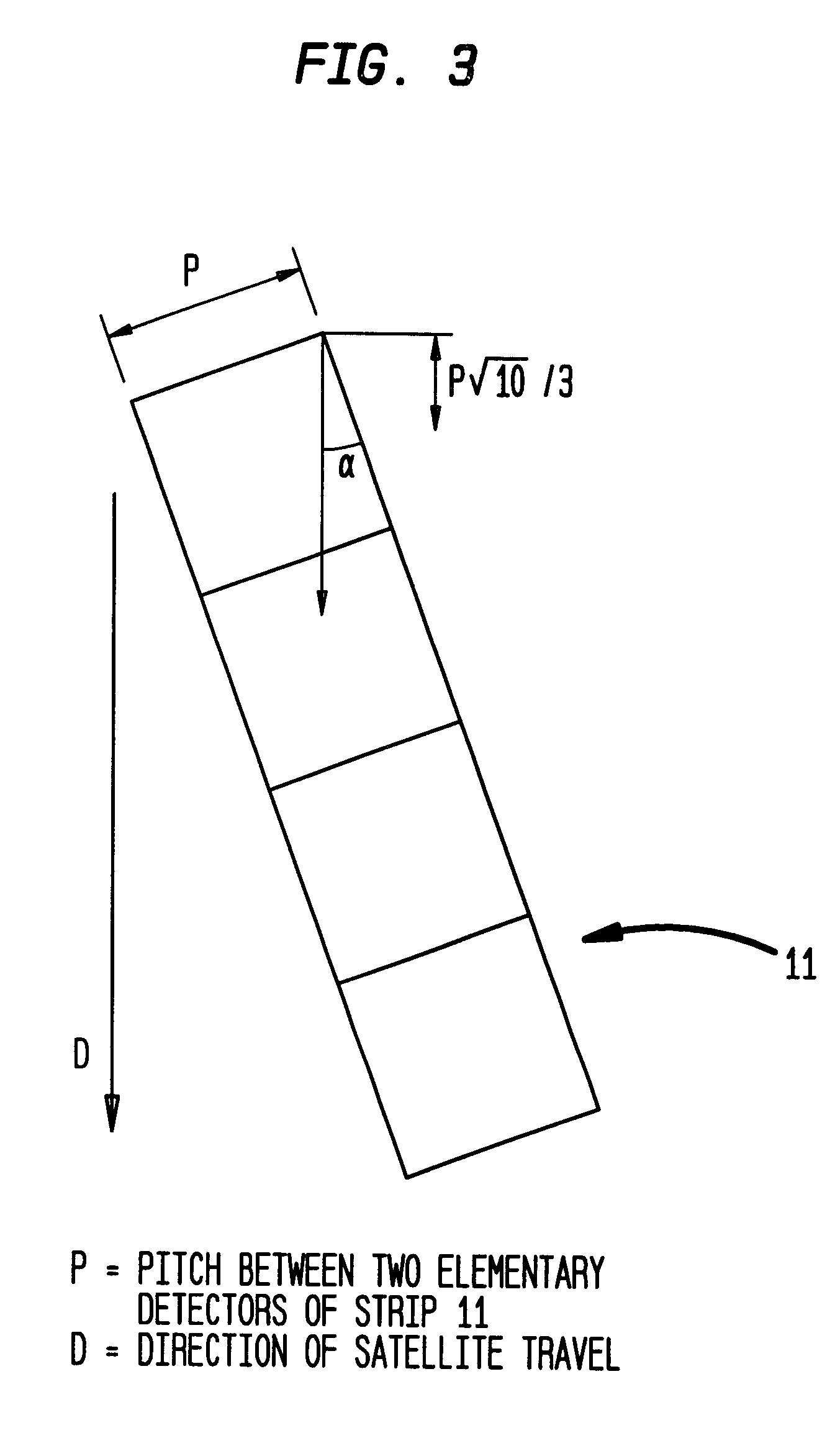
FIGS. 3 and 4 show a linear strip 11 placed in the focal plane of a satellite observation instrument, and also the projection in said focal plane of the travel direction D of the satellite carrying the strip 11.

The strip 11 is oriented in said focal plane so as to form an angle .alpha. relative to the direction D where .alpha. is equal to arctan(1 / 3).

The sampling pitch .DELTA..tau. in the travel direction D is equal to p10 / 6, where p is the pitch between two elementary detectors of the strip 11.

Such sampling is equivalent to acquiring three images by staggered sampling complying with Shannon's condition, i.e., for example, three images obtained by sampling of the type described in the Applicant's patent application WO 97 / 05451.

Consequently, with sampling of the kind shown in FIGS. 3 and 4, it is possible to obtain a new image, after interpolation, e.g. by adding together the three above-mentioned images corresponding to staggered sampling or by implementing processing of the type de...


PUM


Abstract

An improvement to a method of acquiring and processing a satellite observation image of the earth through the use of one strip or a matrix of charge coupled device type detectors. As the detectors travel over an observed zone, a plurality of pixels are acquired in a sampling method. The sampling method includes "e" subarrays corresponding to sampling thereby satisfying Shannon's condition. The "e" is an integer or rational number greater that 1. Processing is implemented that enables a noise-reduced image to be interpolated at a resolution corresponding to that of a sampling subarray on the basis of initially acquired image pixels.

Description

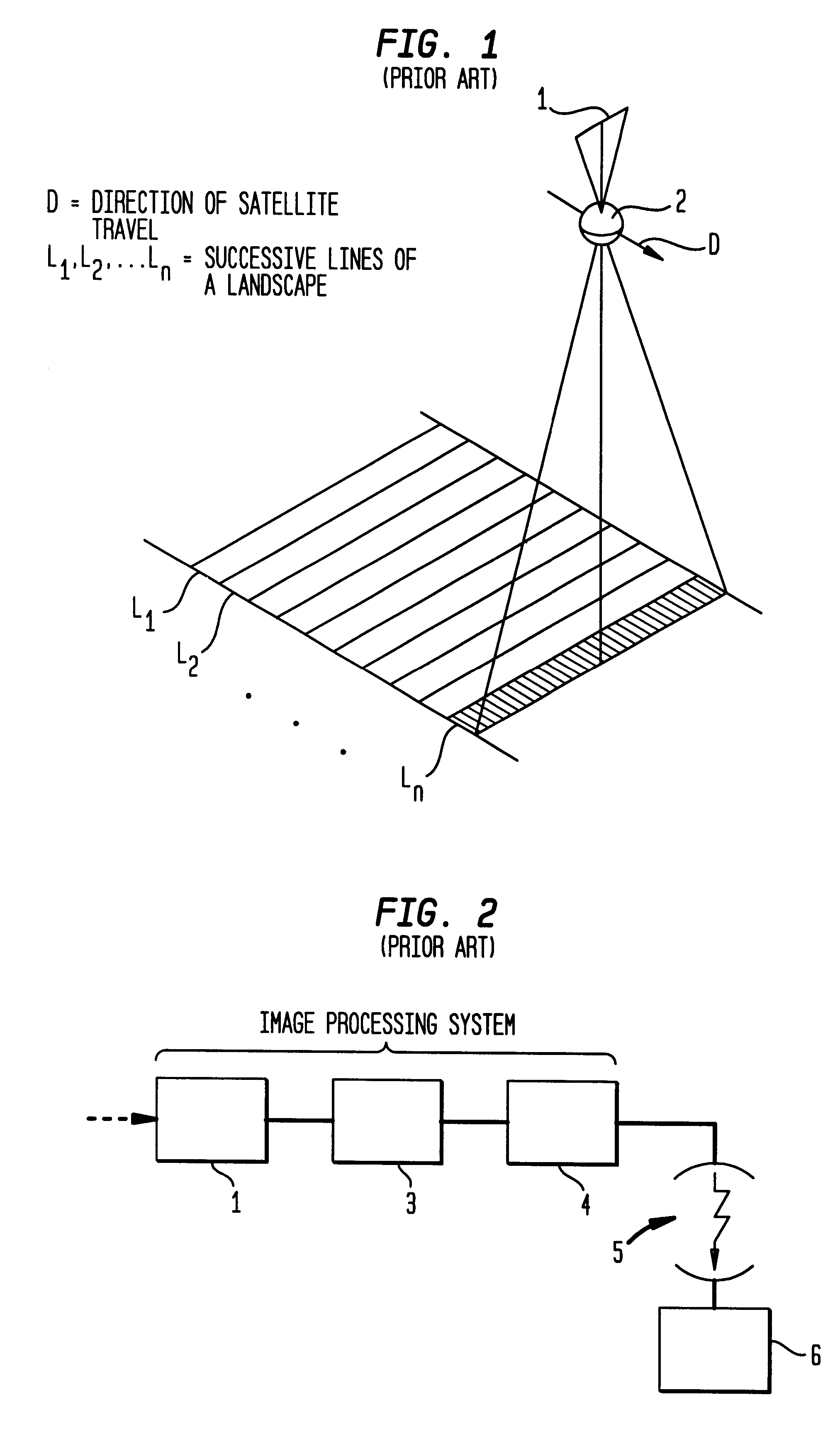
The present invention relates to acquiring a satellite observation image of the earth by push-broom scanning using one or more strips (or matrix(ces)) of detectors of the charge coupled device (CCD) type travelling relative to the observed zone.The principle of push-broom type scanning is shown in FIG. 1 for the case of a single strip 1 of detectors.As the satellite carrying the strip 1 travels, the strip observes successive lines L.sub.1, L.sub.2, . . . , L.sub.n perpendicular to the travel direction (arrow D). At each instant, an optical system 2 of the instrumentation forms the image of a line of landscape on the line of detectors, with the strip 1 being placed in the focal plane of the optical system 2, perpendicularly to the speed vector of the satellite. The landscape scans over each detector which integrates light flux over an exposure time and transforms it into a proportional electric charge.FIG. 2 shows a conventional system for processing images taken in this way.That pro...

Claims


Application Information

Patent Timeline
Patent Type & Authority Patents(United States)
IPC IPC(8): H04N3/08H04N3/15H04N3/02G06T1/00G01C11/02H04N5/369
CPCG01C11/025H04N3/08H04N3/1581H04N3/1593H04N25/701H04N25/41
Inventor ROUGE, BERNARDMOREL, JEAN-MICHEL
Owner CENT NAT DETUD SPATIALES C N E S
Learn More