Wide frequency band micromachined capacitive microphone/hydrophone and method

a micromachined capacitive microphone and micromachined technology, applied in frequency response correction, mechanical vibration separation, instruments, etc., can solve the problems of low sensitivity and lack of robustness

Inactive Publication Date: 2002-12-10
THE BOARD OF TRUSTEES OF THE LELAND STANFORD JUNIOR UNIV
View PDF5 Cites 58 Cited by
  • Summary
  • Abstract
  • Description
  • Claims
  • Application Information

AI Technical Summary

Problems solved by technology

This approach suffers from low sensitivity, especially at low frequencies, and lack of robustness when it comes to use outdoors in humid environments.

Method used


Image

  • Wide frequency band micromachined capacitive microphone/hydrophone and method
  • Wide frequency band micromachined capacitive microphone/hydrophone and method
  • Wide frequency band micromachined capacitive microphone/hydrophone and method

Examples


Embodiment Construction

)

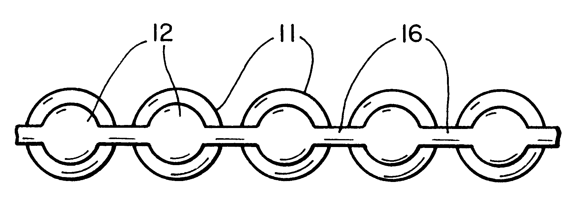
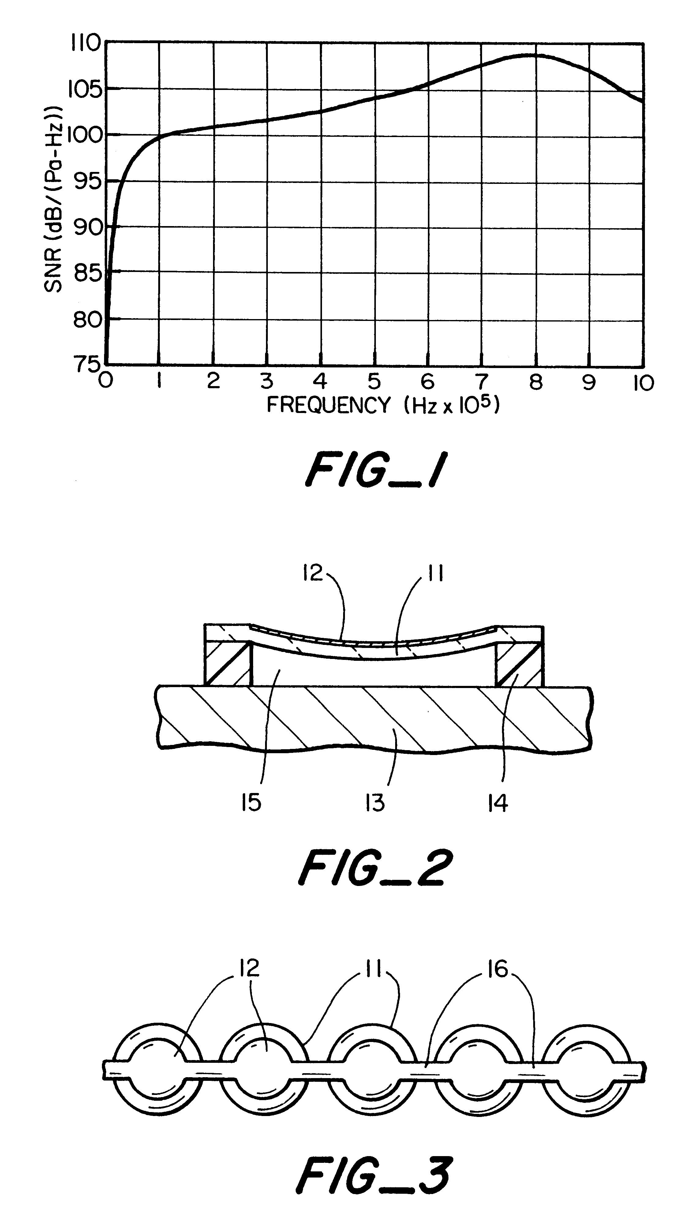
We approach the problem of making a good microphone from a different perspective. Consider the traditional capacitor micromachined ultrasonic transducers (cMUT) described in U.S. Pat. No. 5,619,476, 5,870,351 and 5,894,452. In particular, consider as a theoretical example a device made with 100 cells where each cell has a diameter of 200 .mu.m, a gap of 0.5 .mu.m, and a membrane thickness of 1 .mu.m. Consider that, in this device, all the individual cells are sealed such that the gap of the capacitor is not open to the environment, and thus can survive humid, indeed even wet environments. When used as a receiver, using the traditional detection scheme, with a dc voltage of 30.745 volts applied across the cells with the output applied to an amplifier with the following characteristics: R.sub.in =2 M.OMEGA., C.sub.in =1 pF, V.sub.noise =1.4 nV / Hz, and I.sub.noise =0.01 pA / Hz, the signal to noise ratio of the received signal is shown in FIG. 1. It is seen in FIG. 1 that though the res...


PUM


Abstract

A wide frequency band micromachined microphone including a plurality of micromachined cells of the type including electrodes carried by a membrane supported above a common electrode with conductive lines interconnecting the electrodes is described. A method of operating a microphone array is also described.

Description

This invention relates generally to a wide frequency band capacitive microphone and method and more particularly to a microphone which includes a plurality of micromachined capacitive elements and more particularly to a microphone in which the capacitive elements are connected as a transmission line whereby vibrations of the microphone membranes modulate the length of the transmission line, and still more particularly to acoustic signal direction sensing microphones, pressure sensing transducers, wireless microphones and hydrophones.A good microphone has several qualities: it must be able to detect a minimum pressure of 2.times.10.sup.-5 Pa of pressure that corresponds to the minimum detectable sound level by the human ear, and it must operate over a broad frequency range. A recent stated frequency range requirement for many military applications is 1 mHz-200 KHz. Another requirement is robustness in that the microphone has to be operable outdoors without humidity and condensation d...

Claims


Application Information

Patent Timeline
Patent Type & Authority Patents(United States)
IPC IPC(8): G01H11/00G01H11/06G01S3/808G01S7/00
CPCB06B1/0292G01H11/06H04R3/06H04R19/04G01S3/808G01S7/003H04R1/44
Inventor KHURI-YAKUB, BUTRUS T.ATALAR, ABDULLAHERGUN, ARIF S.DEGERTEKIN, F. LEVENT
Owner THE BOARD OF TRUSTEES OF THE LELAND STANFORD JUNIOR UNIV
Why Eureka
Try Eureka