
Thermodynamic cycle using hydrostatic head for compression

a thermodynamic cycle and hydrostatic head technology, applied in the direction of insulation, domestic cooling apparatus, borehole/well accessories, etc., can solve the problems of increasing safety risks, cycle operating costs, and energy consumption to effect compression, and achieve the effect of reducing the cost of compressing the gas

Inactive Publication Date: 2002-12-17
EXXONMOBIL UPSTREAM RES CO
View PDF18 Cites 13 Cited by
  • Summary
  • Abstract
  • Description
  • Claims
  • Application Information

AI Technical Summary

Benefits of technology

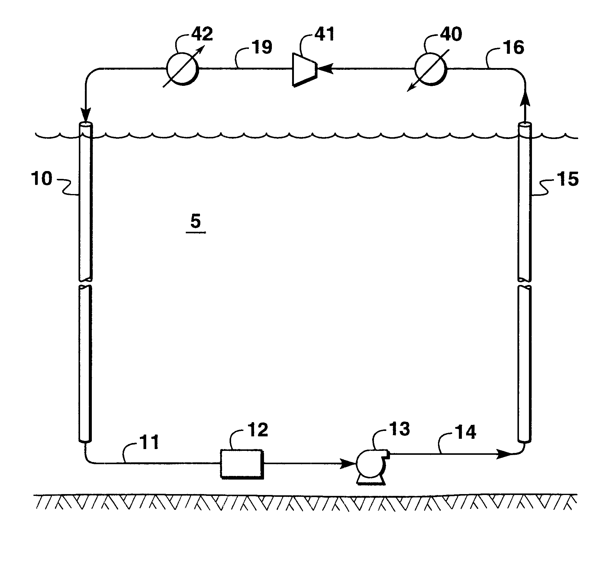
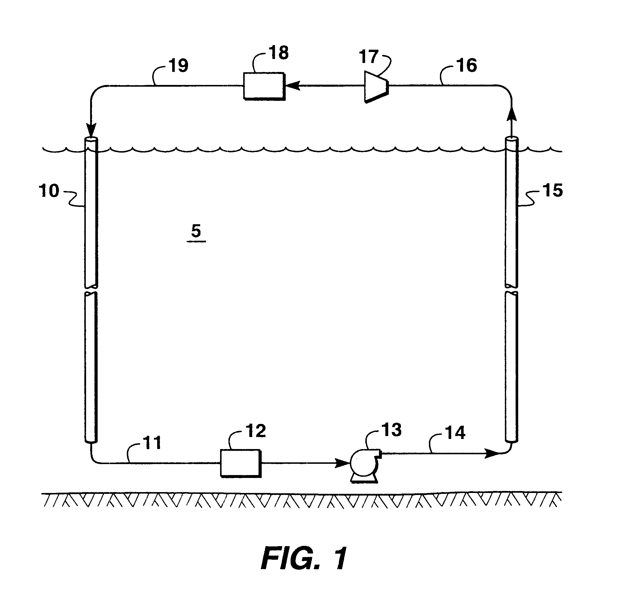
In this embodiment of the present invention eliminates the need for the mechanical compressor of a conventional refrigeration system. Compression and heat rejection phases of this refrigeration system are simultaneously performed in a down riser. A heat-exchange medium pump is the only moving part of the refrigeration system. Compression of the heat-exchange medium is virtually isothermal at the temperature of the heat sink.
The present invention can substantially reduce the cost of compressing the gas to a liquid compared to the cost of an adiabatic process performed by a conventional compressor. One advantage of this invention over power cycles used in the past is that gravity is used to carry out a substantial portion of the compression of the heat-exchange medium.

Problems solved by technology

In these cycles, the cost of energy to effect compression is a significant part of the cycles' capital cost as well as the cycles' operating cost.
Having a compressor on an offshore structure takes up space and increases safety risks associated with having a mechanical apparatus using a pressurized heat-exchange medium which is often combustible.

Method used


Image

  • Thermodynamic cycle using hydrostatic head for compression
  • Thermodynamic cycle using hydrostatic head for compression
  • Thermodynamic cycle using hydrostatic head for compression

Examples


example

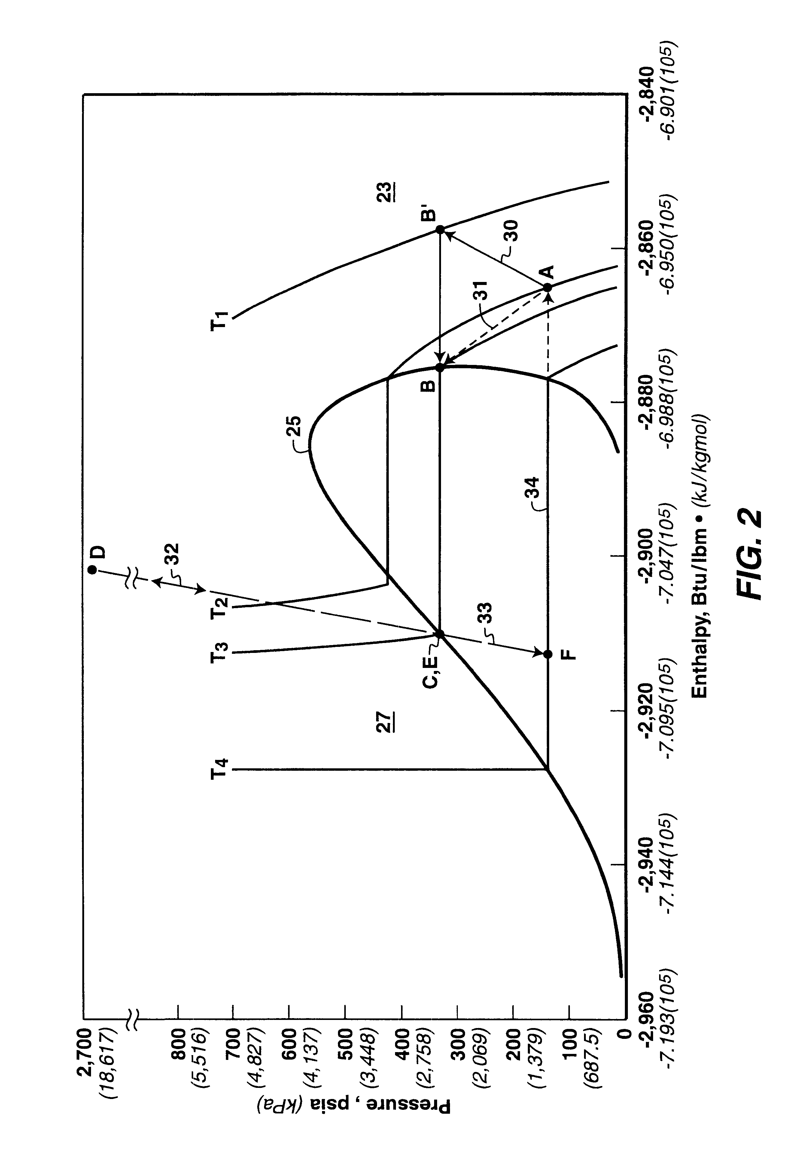
A simulated mass and energy balance was carried out to illustrate the preferred embodiment of the invention as described by FIG. 1, and the results are set forth in the Table below. The data in the Table assumed the heat-exchange medium was Freon (R-13) and that the evaporator temperature was about -26.degree. C. (-15.degree. F.). This corresponded to an evaporator pressure of about 945 kPa (137 psia). The down riser 10 was assumed to be 1524 meters from top to bottom. The pumping by pump 13 was assumed to be isentropic and the flow in the down riser 10 and the return riser 15 was assumed to be frictionless. In this example, a heat exchanger 12 was not used.

The data presented in the Table are offered to provide a better understanding of the present invention, but the invention is not to be construed as unnecessarily limited thereto. The temperatures and flow rates are not to be considered as limitations upon the invention which can have many variations in temperatures and flow rates...


PUM


Abstract

A thermodynamic cycle is disclosed that uses compression and expansion to generate refrigeration or power in which at least some of the compression is effected by hydrostatic head of the heat-exchange medium used in the cycle. In a refrigeration cycle, the head of a heat-exchange medium in the refrigeration cycle is used to compress the heat-exchange medium. A vaporous heat-exchange medium is introduced into the upper end of a down riser that extends downwardly through a heat sink. The vaporous heat-exchange medium descends through the down riser and the head of the heat-exchange medium compresses the heat-exchange medium. The heat generated by the compression is transferred to the heat sink. The heat-exchange medium is then pumped up through a return riser and passed through a pressure expansion means and evaporator. From the evaporator the heat-exchange medium is returned to the upper end of the down riser for recycling.

Description

FIELD OF THE INVENTIONThe invention relates generally to an improved thermodynamic cycle in which a heat-exchange medium goes through a cyclic process of compression, condensation, and expansion to produce power or to produce cooling. More specifically, the invention relates to an improved thermodynamic cycle that uses hydrostatic head to effect compression.BACKGROUND OF THE INVENTIONThermodynamic power-producing cycles and refrigeration cycles use various cyclic combinations of compression, heat rejection, expansion, and heat addition. In these cycles, the cost of energy to effect compression is a significant part of the cycles' capital cost as well as the cycles' operating cost.Common features of thermodynamic power-producing cycles include (1) a compression process wherein one or more compressors or pumps increase the pressure of a heat-exchange medium, (2) a thermal addition process in which energy is added to he heat-exchange medium from a suitable heat source such as air, wate...

Claims


Application Information

Patent Timeline
Patent Type & Authority Patents(United States)
IPC IPC(8): F01K25/00F01K25/08E21B36/00F03G7/05F03G7/00F25B1/00F25B9/02F25B11/02F25B9/00
CPCE21B36/001F01K25/08F03G7/05F25B1/00F25B9/002F25B9/02F25B11/02F25B2309/06Y02E10/34Y02E10/30
Inventor KELLEY, BRUCE T.
Owner EXXONMOBIL UPSTREAM RES CO
Learn More