Physiological sensor array

a sensor array and sensor technology, applied in the field of physiological sensor devices or sensor arrays, can solve the problems of small sensor, limited ecg signal measurement, and a large amount of bulky apparatus as a whol

Inactive Publication Date: 2002-12-17
CLEARPATH PARTNERS
View PDF130 Cites 274 Cited by
  • Summary
  • Abstract
  • Description
  • Claims
  • Application Information

AI Technical Summary

Benefits of technology

Another aspect of the invention provides a physiological sensor device for attachment to a mammalian subject comprising a sensor for acquiring physiological data about the subject in use, and an output transmitter which receives a signal representative of the physiological data from the sensor and transmits the signal to a remote location, wherein the output transmitter comprises an inductive element for inductively coupling the output transmitter to a remote receiver at the remote location. Beneficially the inductive coupling enables efficient low powered transfer of data from the device.
Preferably, the output transmitter comprises a reservoir capacitor and the inductive element, which together improve the power efficiency of transmission. Also, the inductive element preferably has first and second ends each of which ends is connected via one of a pair of switches to the supply lines within the output transmitter to enable a reversing of the polarity across the inductive element. Preferably, the inductive element comprises a coil which forms part of an and after "H-bridge" circuit in the output transmitter. In a preferred embodiment the inductive element comprises a rectangular, substantially flat coil.

Problems solved by technology

The device is disposable after one use but, as a result, is somewhat crude and only comprises two electrodes for very basic ECG measurements.
While fairly sophisticated, this arrangement only contemplates point-in-time 12 lead ECG studies and is not disposable.
However, this small sensor is limited to measuring ECG signals.
The various sensors are connected by cabling and accordingly the apparatus as a whole is quite bulky.

Method used


Image

  • Physiological sensor array
  • Physiological sensor array
  • Physiological sensor array

Examples


Embodiment Construction

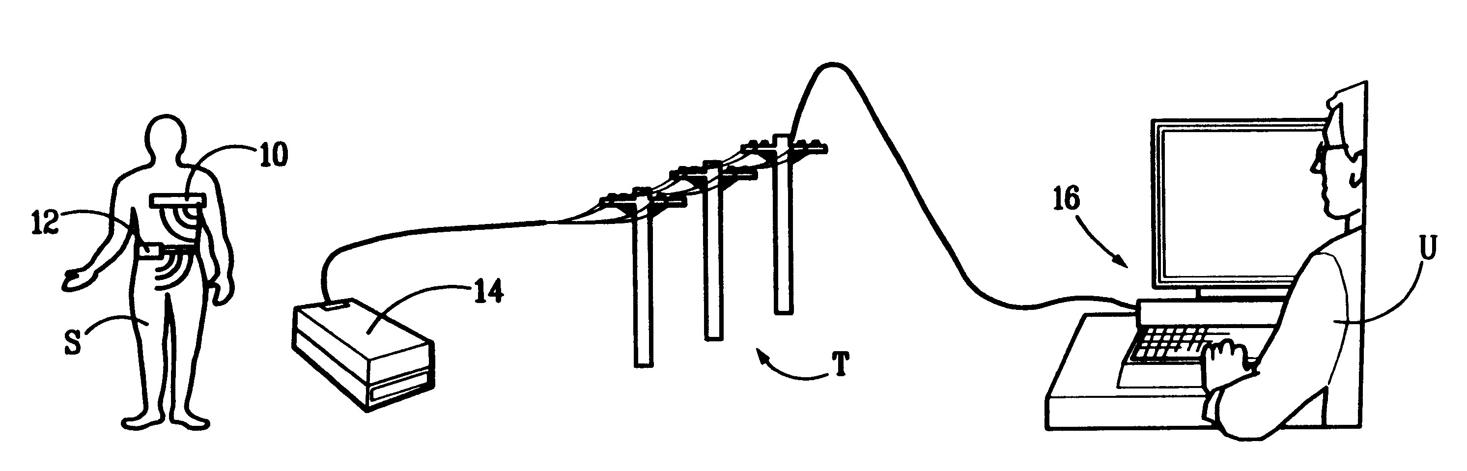
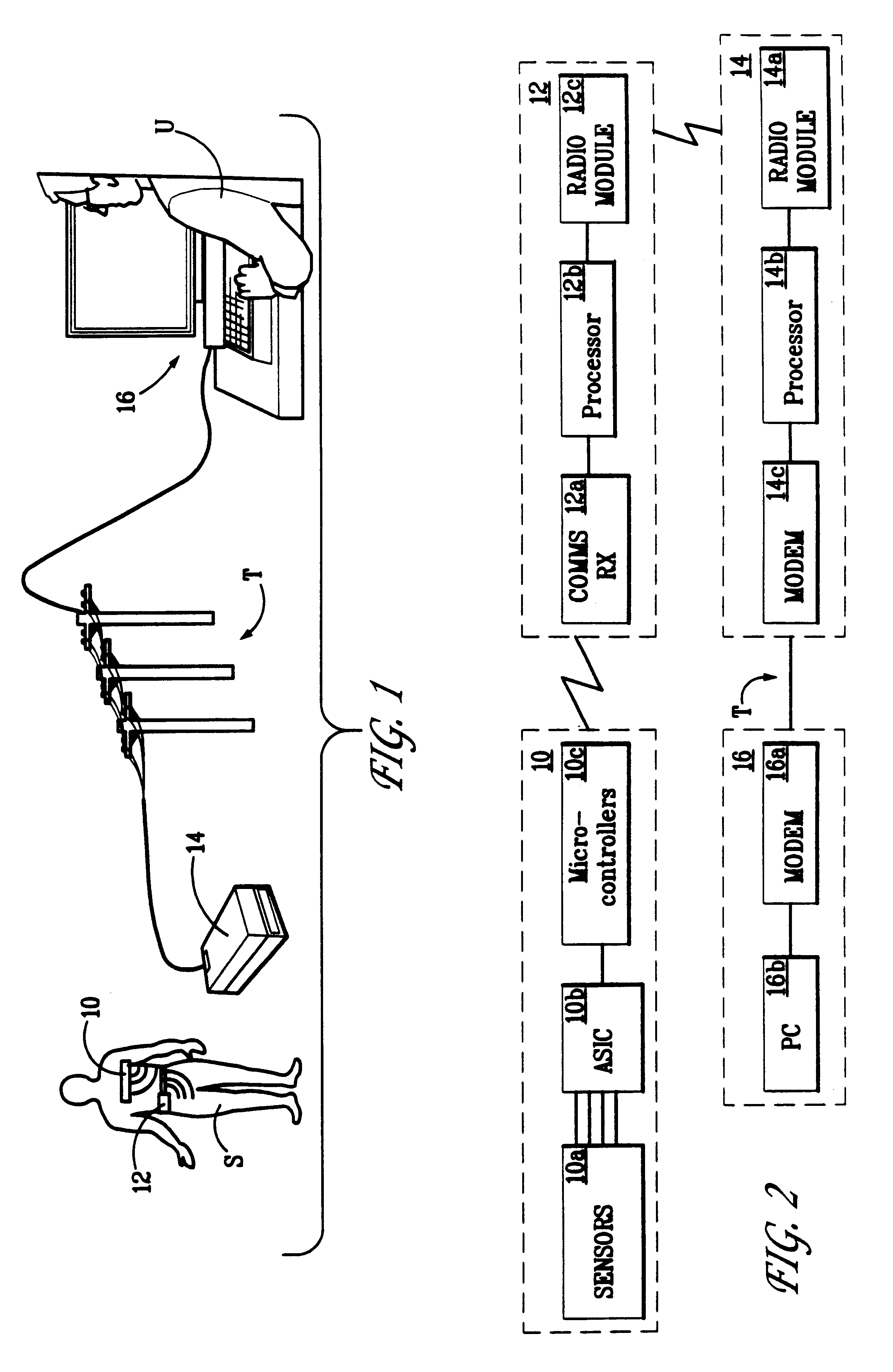
FIG. 1 illustrates a physiological sensor device or array 10 according to the invention as attached to the chest of a human subject or patient S. Device 10 comprises an array of sensors 10a (to be described later), which generate data about the physiological condition of the subject. This data is transmitted to a portable signal transfer unit 12. In turn, signal transfer unit 12 transfers a signal representative of the measured physiological parameters to a base station 14 which operably communicates with a remote monitoring station 16, which can comprise a suitably programmed computer 16b. This communication is, for example, via a telemetry or telephonic link T, such as a land based telephone system, using, for example, modems 14c and 16a.

The basic structure of the different components in the system is shown in the schematic block diagram of FIG. 2. As can be seen, device 10 comprises an array of sensors 10a in communication with suitable electronics forming a controller for proces...


PUM


Abstract

A physiological sensor device for attachment to a mammalian subject comprising an output transmitter, at least two physiological sensors each for sensing one of the subject's physiological parameters, and a controller operably in communication with the physiological sensors which controller communicates a signal comprising data representative of both the sensed physiological parameters to the output transmitter which operably transmits the signal to a remote location, wherein the controller comprises a multiplexer which operably switches the data from both the physiological sensors into a serial output signal. Respiration may be detected by a bend sensor including an elongate member and an electrical component mounted thereon which electrical component has an electrical property which varies in dependence on the extent of bending of the elongate member. Other parameters such as temperature and full waveform ECG may also be measured.

Description

1. Field of the InventionThe present invention relates to a physiological sensor device or sensor array for attachment to a mammalian subject in order to obtain data about one or more physiological parameters of the subject. In particular, the invention relates to a physiological in sensor device in the form of a patch attachable to the chest of a human subject to enable sensing of physiological data such as electro-cardiographic data and / or respiration data.2. Description of the Prior ArtThe prior art includes U.S. Pat. No. 3,943,918 to Lewis which discloses an ECG signal sensing and transmitting device for use in the care of medical patients requiring monitoring of cardiac functions. The device disclosed is a single use, disposable unit consisting principally of a foam pad having a pair of circular electrodes in one face of the rectangular foam block. The block comprises electrical circuitry which transmits an RF signal to a receiver which is required to be within 100 feet of the ...

Claims


Application Information

Patent Timeline
Patent Type & Authority Patents(United States)
IPC IPC(8): A61B5/0408A61B5/00H04M11/00A61B5/0205A61B5/11A61B5/113G08C19/00A61B5/08A61B5/308G01D21/00
CPCA61B5/0002A61B5/04085H04M11/002A61B5/0205A61B5/1135Y10S128/903A61B5/282
Inventor NEW, JR., WILLIAMHARRY, ANDREA J.JOHNSON, PAULKUMAR, HARPAL S.MULLARKEY, WILLIAM J.NICOLSON, LAURENCE J.PLACE, JOHN D.
Owner CLEARPATH PARTNERS
Why Eureka
Try Eureka