Apparatus and method for electron beam evaporation

a technology of electron beam and apparatus, which is applied in the direction of ion implantation coating, chemical vapor deposition coating, coating, etc., can solve the problems of troublesome evaporation characteristics of the apparatus used, inability to use the optical coating, and inability to evaporate the optical coating

Inactive Publication Date: 2002-12-17
LEYBOLD OPTICS
View PDF14 Cites 2 Cited by
  • Summary
  • Abstract
  • Description
  • Claims
  • Application Information

AI Technical Summary

Problems solved by technology

Another difficulty consists in the various evaporation characteristics of the coating material in use.
Such an apparatus is not suitable for use in optical coating, since it is too expensive.
The variable range for the positioning of the evaporation point in optical coating apparatus of the prior art is only around 0.05 to 0.5 m. Furthermore, the vapor coating of the tube and contamination of the optical coating by the hydraulic oil are troublesome.

Method used


Image

  • Apparatus and method for electron beam evaporation
  • Apparatus and method for electron beam evaporation
  • Apparatus and method for electron beam evaporation

Examples


Embodiment Construction

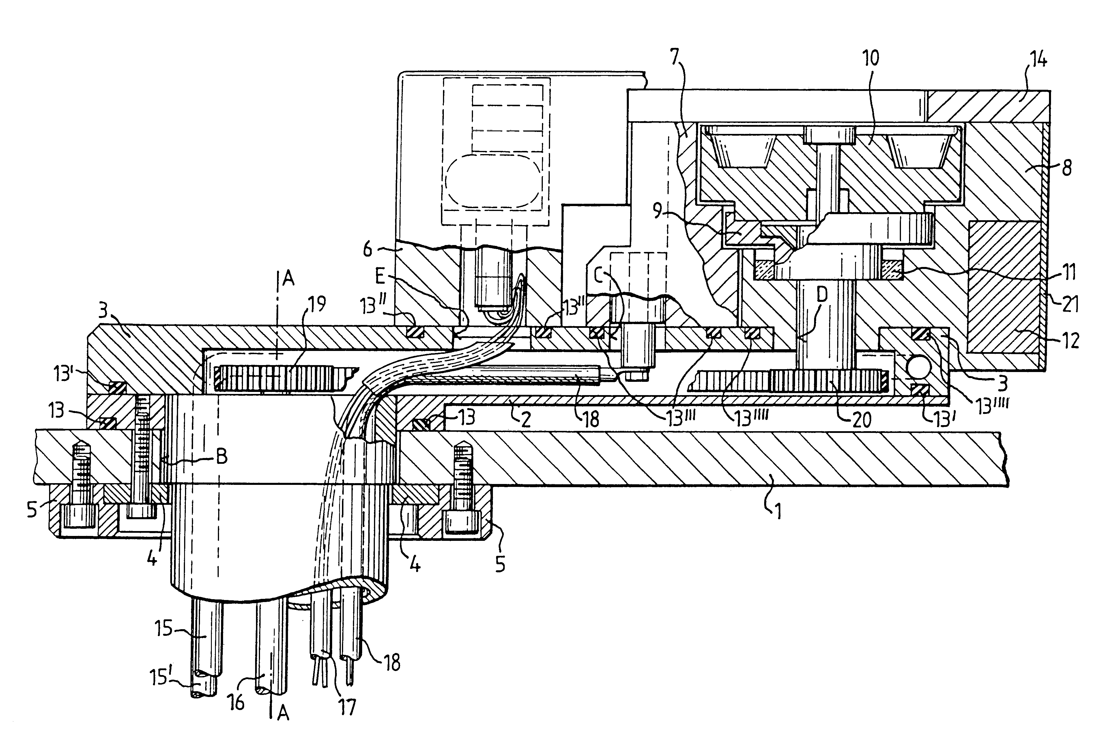
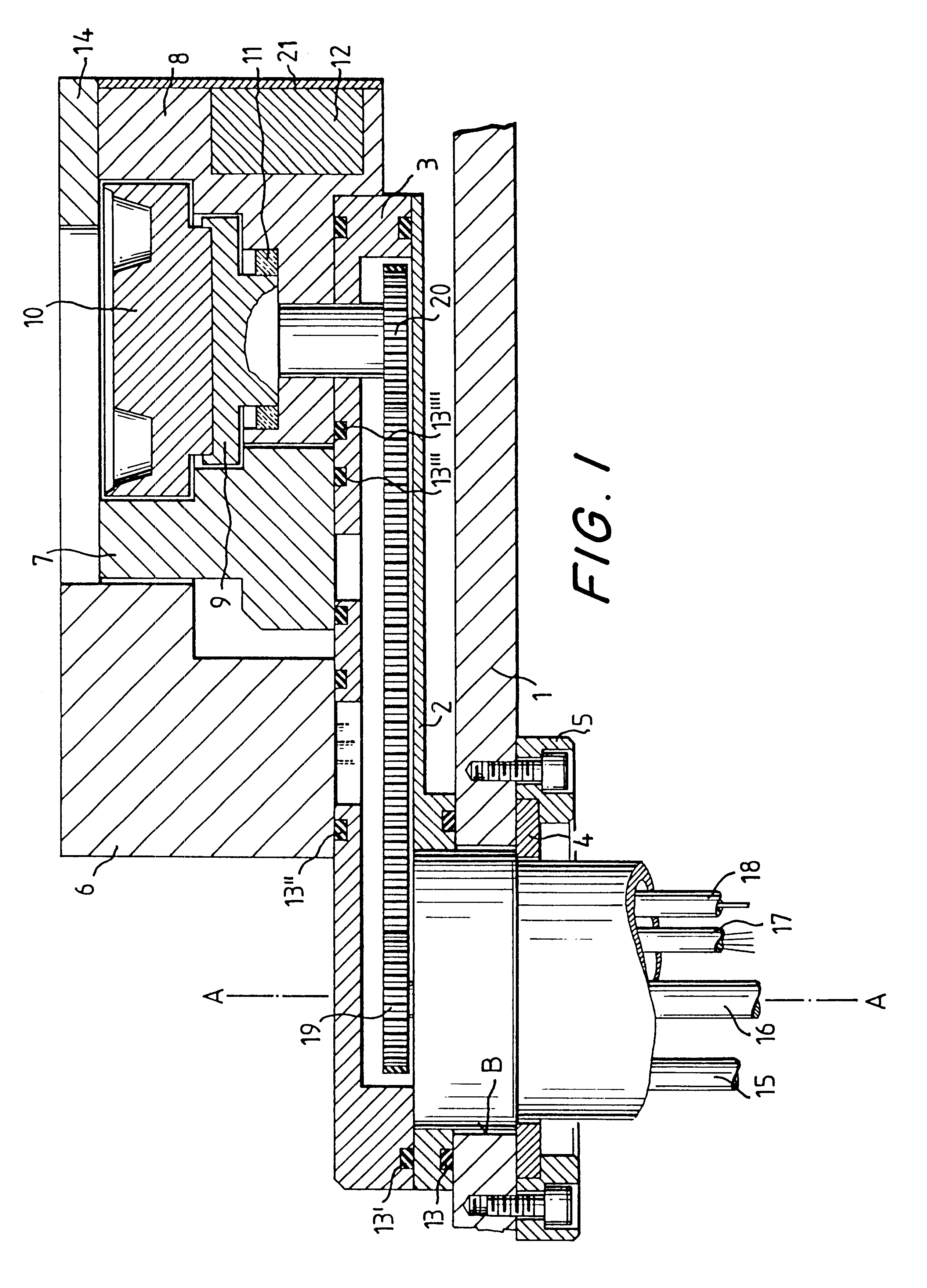
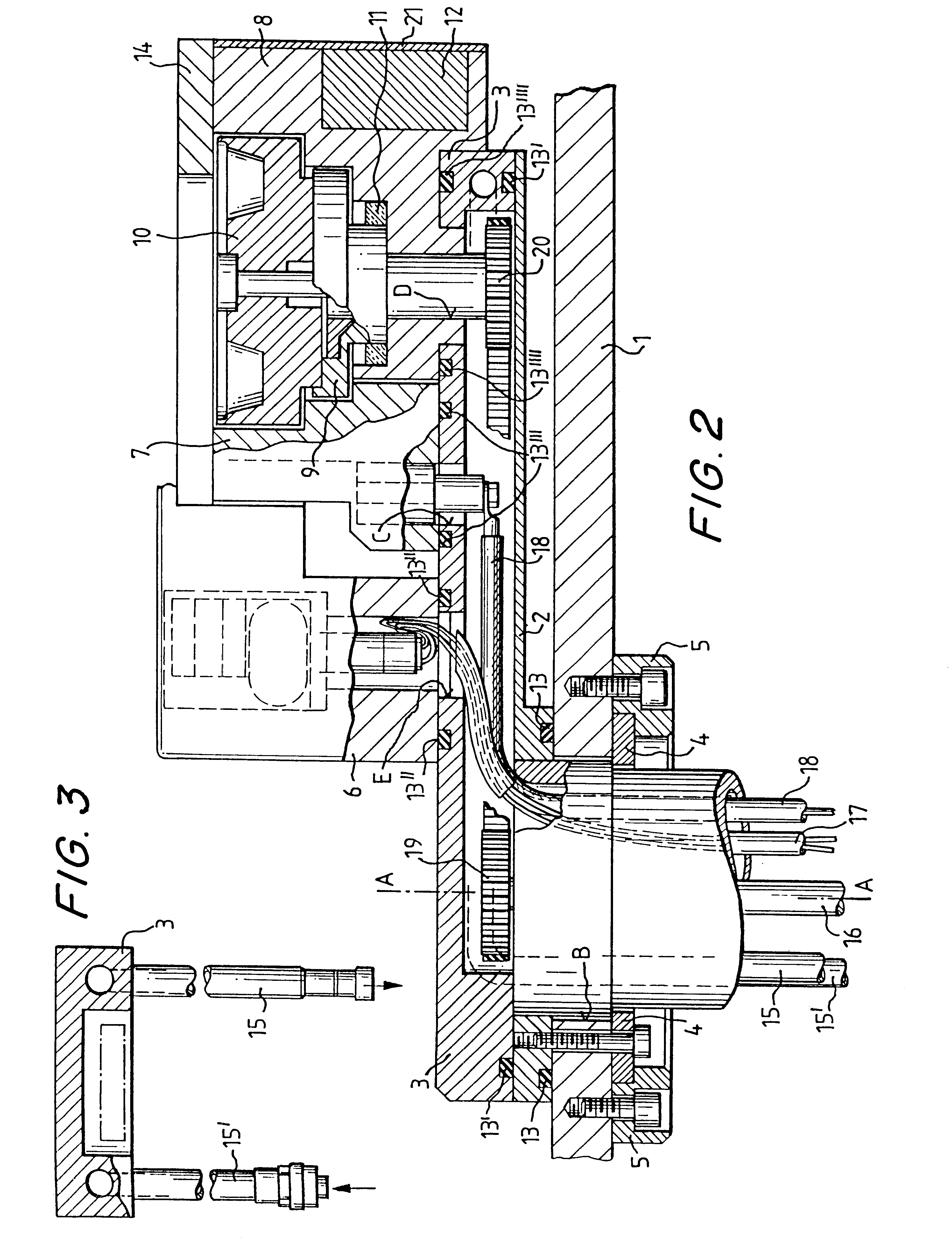
The apparatus of the invention is represented in FIG. 1. The base plate 1 of the tank has a bore 22 which serves to hold the entire apparatus. The bearing plate 2 which is attached to base plate 1, is held to bore 22 by means of chamber flange 5 and counter-plate 4. Bearing plate 2 can be rotated about central axis 24 after loosening chamber flange 5. A cover plate 3 of channel-shaped cross section is placed on the bearing plate 2 in a vacuum-tight manner by means of the gasket 13'. The hollow space formed is in communication with the atmosphere and serves to accommodate the drive means and supply lines. Cover plate 3 and bearing plate 2 disposed to form a hollow interior therebetween comprise the carrier plate for the evaporator. FIG. 2 shows the apparatus of FIG. 1 with cut-out views of the components of the electron beam evaporator and the flat hollow carrier plate. The individual modules of the electron beam evaporator are sealed hermetically by O-rings on the upper, vacuum side...


PUM

PropertyMeasurementUnit
voltageaaaaaaaaaa
distanceaaaaaaaaaa
thicknessaaaaaaaaaa

Abstract

Disclosed is an electron beam evaporator for installation in a vacuum apparatus which provides for variable positioning during or between applications of a coating. The apparatus has a carrier plate which is a flat hollow body, the top cover plate of which supports the evaporator. The hollow body is disposed over the bore in the tank such that it can be turned about the main axis of the bore. The component assemblies of the electron beam evaporator are vacuum-tight on the cover plate and the connecting lines are carried through the interior of the hollow body to the component assemblies.

Description

BACKGROUND OF THE INVENTIONThe invention relates to an electron-beam evaporator for vacuum coating apparatus as used, for example, in optics for tempering lenses or eyeglass lenses. For this purpose the substrates to be coated are moved on an appropriate substrate holder over the vapor source heated by the electron beam, and are thus coated. The evaporation point from which the vapor is released is usually off-center from the main axis of rotation of the substrate holder.The multiplicity of different substrate shapes and surface curvatures call for special efforts to achieve the desired coating thickness tolerances and coating thickness distribution within a batch on the substrate holder in the vapor coating apparatus. Another difficulty consists in the various evaporation characteristics of the coating material in use. For this reason it is desirable to have a variable or adjustable positioning of the evaporation point with respect to the substrates being coated, so that an optimum...

Claims


Application Information

Patent Timeline
Patent Type & Authority Patents(United States)
IPC IPC(8): H01J37/305C23C14/30H01J37/30
CPCH01J37/3053H01J2237/3132
Inventor LOCHER, STEFANWIRTH, ECKHARD
Owner LEYBOLD OPTICS
Why Eureka
Try Eureka