Induction heating device and method, and processor

a heating device and heating method technology, applied in the field of induction heating devices, can solve problems such as complete inacceptability

Inactive Publication Date: 2002-12-17
AGFA GEVAERT HEALTHCARE
View PDF10 Cites 14 Cited by
  • Summary
  • Abstract
  • Description
  • Claims
  • Application Information

AI Technical Summary

Benefits of technology

It is therefore the object of the present invention to make possible a temperature distribution on the surface of a cylindrical body which, with a compact design, meets the requirements placed on the thermal development of a recording medium.
It is preferable for the at least one auxiliary induction coil to be capable of activation by being short-circuited. This implementation provides the advantage that it is possible to dispense with an additional power supply unit for driving the at least one auxiliary induction coil.
Preferably, a control device can further be provided, in order to activate at least one auxiliary induction coil. The control device can comprise a look-up table, in which the characteristic for the activation of the at least one auxiliary induction coil for at least one load case is stored. By this means, the at least one auxiliary induction coil can be operated with regard to the load case which is currently present, for example start-up of the processor or standby operation. Also stored in such a look-up table are the appropriate drive data for driving the at least one auxiliary induction coil. If a specific look-up table is compiled for a specific induction heating device, a further advantage results from the fact that the production tolerances for this specific induction heating device, in particular the production tolerances for the primary and auxiliary induction coils and for the thickness and coating of the cylindrical body, can be reduced, since deviations can be compensated for electronically by driving the induction coils appropriately.

Problems solved by technology

In particular in this area, it is completely unacceptable if there is a risk of misdiagnosis as a result of non-uniform development.

Method used


Image

  • Induction heating device and method, and processor
  • Induction heating device and method, and processor
  • Induction heating device and method, and processor

Examples


Embodiment Construction

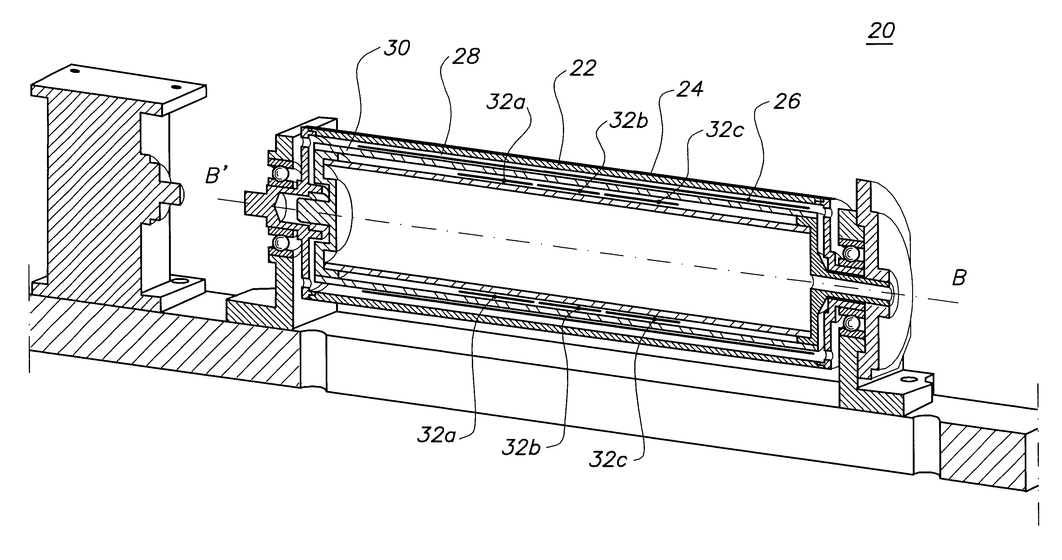
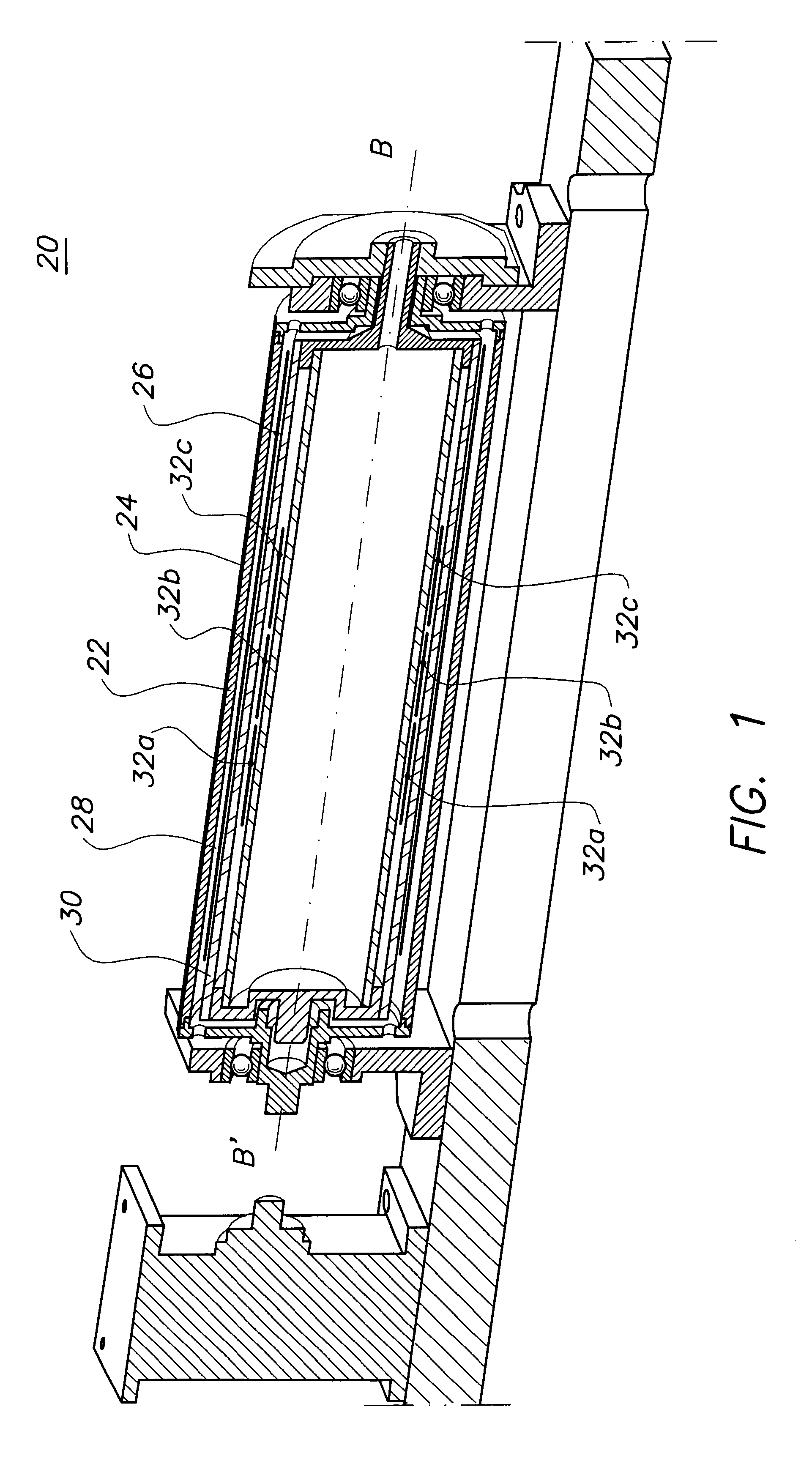
FIG. 1 shows a longitudinal section through an induction heating device 20 according to the invention. It comprises a cylindrical body 22 made of electrically conductive material, by means of which an outer surface 24 is formed, onto which the exposed recording material is pressed, for its thermal development, by pressing means (not illustrated), preferably rollers, brushes and the like. In the induction heating device 20, the cylindrical body 22 is mounted such that it can rotate about its longitudinal axis B'B. Arranged in the cylindrical body 22 is a primary induction coil 26, which can be wound homogeneously (as illustrated) or inhomogeneously (see FIG. 4). The primary induction coil 26 and the cylindrical body 22 form a transformer, the cylindrical body 22 constituting a short-circuited winding. The magnetic field produced by the primary induction coil 26 induces currents in the cylindrical body 22, which lead to development of heat on the surface 24 of the cylindrical body 22....


PUM


Abstract

An induction heating device having a hollow cylindrical body made of electrically conductive material, at least one primary induction coil and at least one auxiliary induction coil, the at least one primary induction coil and the at least one auxiliary induction coil being arranged in the cavity of the cylindrical body such that, by means of the at least one primary induction coil and the at least one auxiliary induction coil, first and second magnetic fields, respectively, can be produced in the cylindrical body. The at least one auxiliary induction coil and the at least one primary induction coil operate such that the second magnetic field, at least in one area of the cylindrical body, counteracts the first magnetic field. A corresponding method of operating such an induction heating device, and also a processor for processing a recording medium, having such an induction heating device, are also provided.

Description

FIELD OF THE INVENTIONThe present invention relates to an induction heating device having a hollow cylindrical body made of electrically conductive material, at least one primary induction coil and at least one auxiliary induction coil, the at least one primary induction coil and the at least one auxiliary induction coil being arranged in the cavity of the cylindrical body in such a way that, by means of the at least one primary induction coil, a first magnetic field can be produced in the cylindrical body and, by means of the at least one auxiliary induction coil, a second magnetic field can be produced in the cylindrical body. It relates moreover to a method of operating an induction heating device, which comprises a hollow cylindrical body made of electrically conductive material, at least one primary induction coil and at least one auxiliary induction coil, the primary induction coil and the at least one auxiliary induction coil being arranged in the cavity of the cylindrical bo...

Claims


Application Information

Patent Timeline
Patent Type & Authority Patents(United States)
IPC IPC(8): H05B6/14
CPCH05B6/145
Inventor NITSCHE, WERNERBETZOLD, WOLFRAMSTUMPF, FRIEDRICH
Owner AGFA GEVAERT HEALTHCARE
Why Eureka
Try Eureka