Assembly method and installation, a device assembled thereby, and a unit including the device

a technology of assembly method and assembly method, which is applied in the direction of building components, applications, windows, etc., can solve the problems of mechanical damage, deformation of elements, and rise of forces, and achieve the effect of avoiding wounding

Inactive Publication Date: 2003-01-07
PPG IND GLASS
View PDF7 Cites 14 Cited by
  • Summary
  • Abstract
  • Description
  • Claims
  • Application Information

AI Technical Summary

Benefits of technology

This provides a continuous bridge with one or more adjacent pads between the envelope elements, with the bridge being strong in compression and capable of absorbing stress without harming the assembly.
It is desirable to give the pad a shape that avoids "wounding" the envelope element during assembly.

Problems solved by technology

In particular, under certain conditions of temperature and / or stress, these elements are deformed because of their low resilience.
For example, the application of stress on laminated glazing, e.g. in the form of compression for holding the glazing in position, often gives rise to creep.
This causes mechanical damage, and spoils the waterproofing of the glazing and / or the unit in which it is integrated.
When that happens, the glazing is no longer properly held or driven.
In particular, the connection between the glazing and the holding and / or drive means is degraded (backlash, vibration, jamming, etc.), and may even be broken.
At present, industrial solutions are unsatisfactory, in particular because of cost.
This weakness the glazing and increases its cost.
Also, the means secured to the glazing are then heavy, whereas, on the contrary, industry is looking for ways of reducing weight.
The same drawback of weight is to be found with means secured by clamping the glazing by means of a yoke.
The size, the reliability, and the simplicity of the unit including the glazing all suffer therefrom.
These drawbacks present further difficulties when faced with increasing requirements of the industry concerning soundproofing, reduction in weight and size, and concerning safety and reliability (ability of the assembly to withstand shock and conditions of heat or humidity, etc.).
Delamination can also occur during assembly or during the aging cycle, and can escape attention during assembly, which is one of the causes of such elamination.
The above problems are described in the context of aminated glazing, but they also occur in numerous other mechanical fields.

Method used


Image

  • Assembly method and installation, a device assembled thereby, and a unit including the device
  • Assembly method and installation, a device assembled thereby, and a unit including the device
  • Assembly method and installation, a device assembled thereby, and a unit including the device

Examples


Embodiment Construction

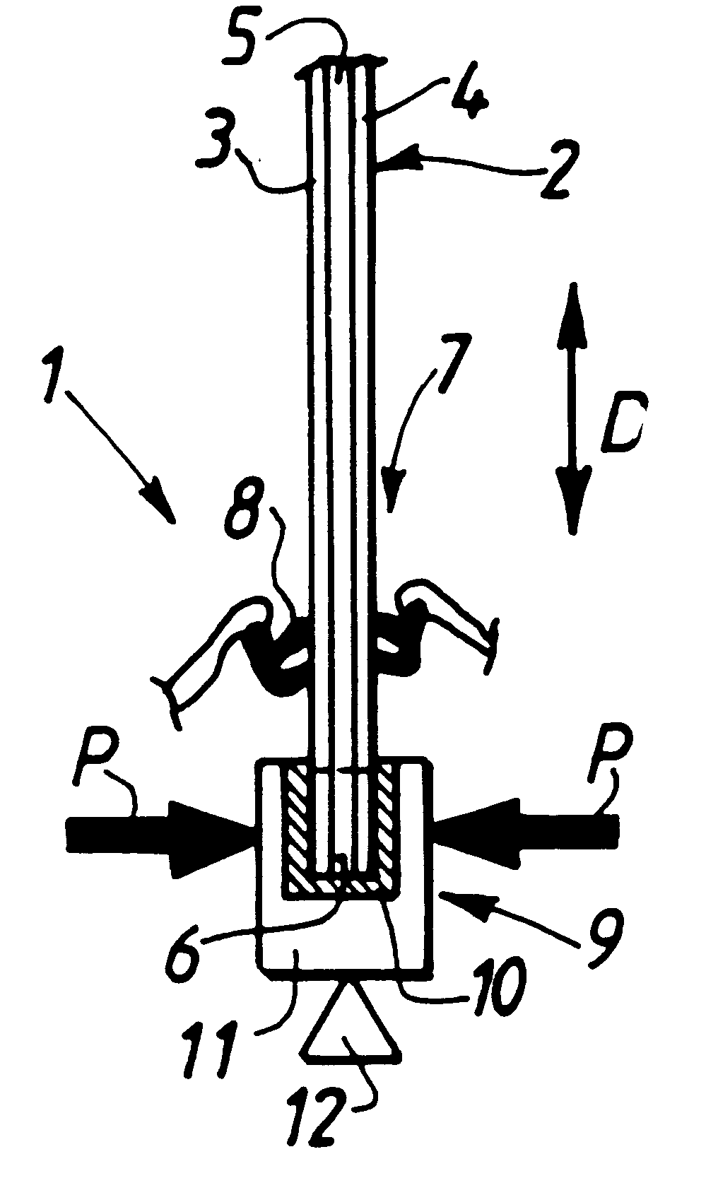
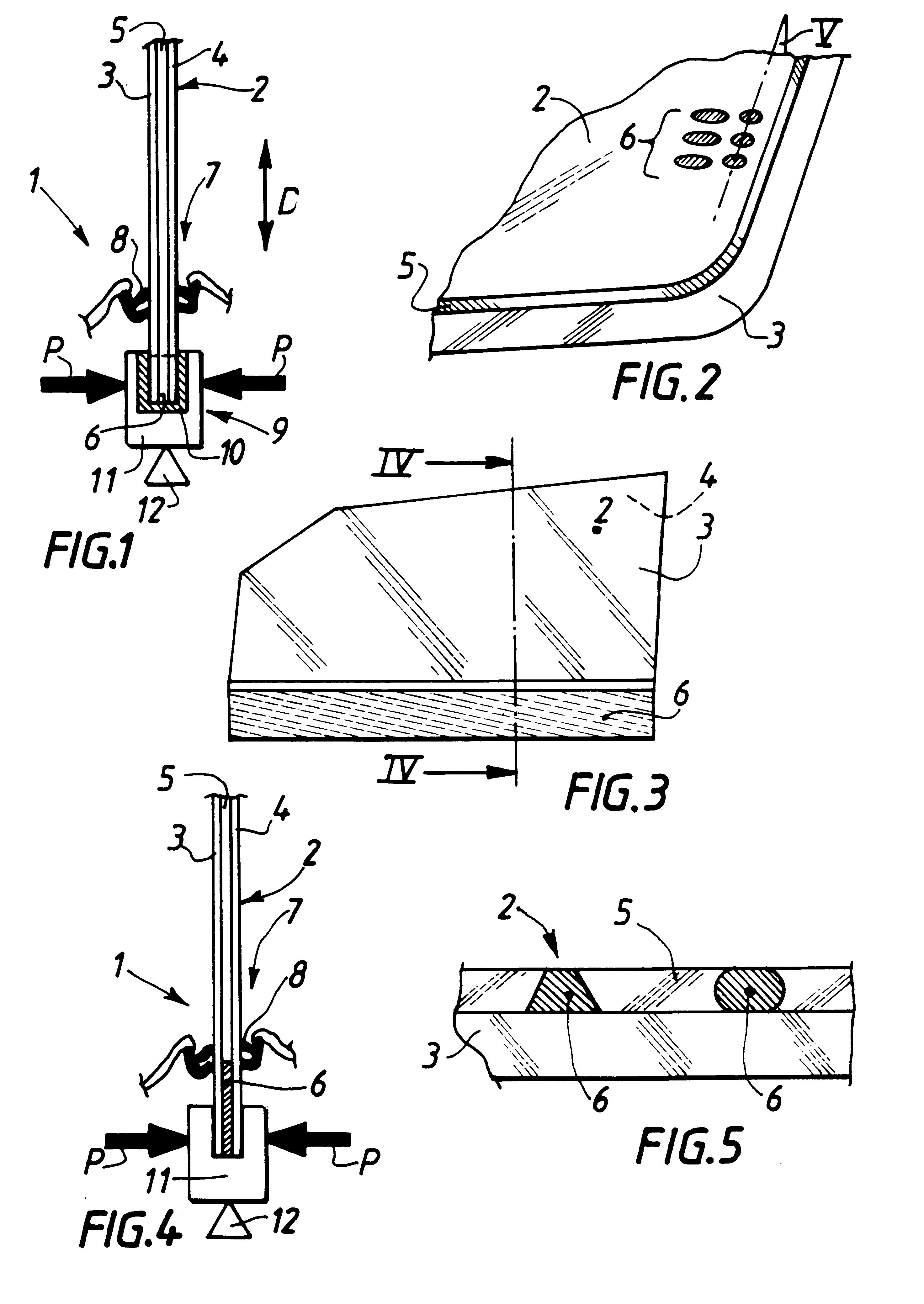
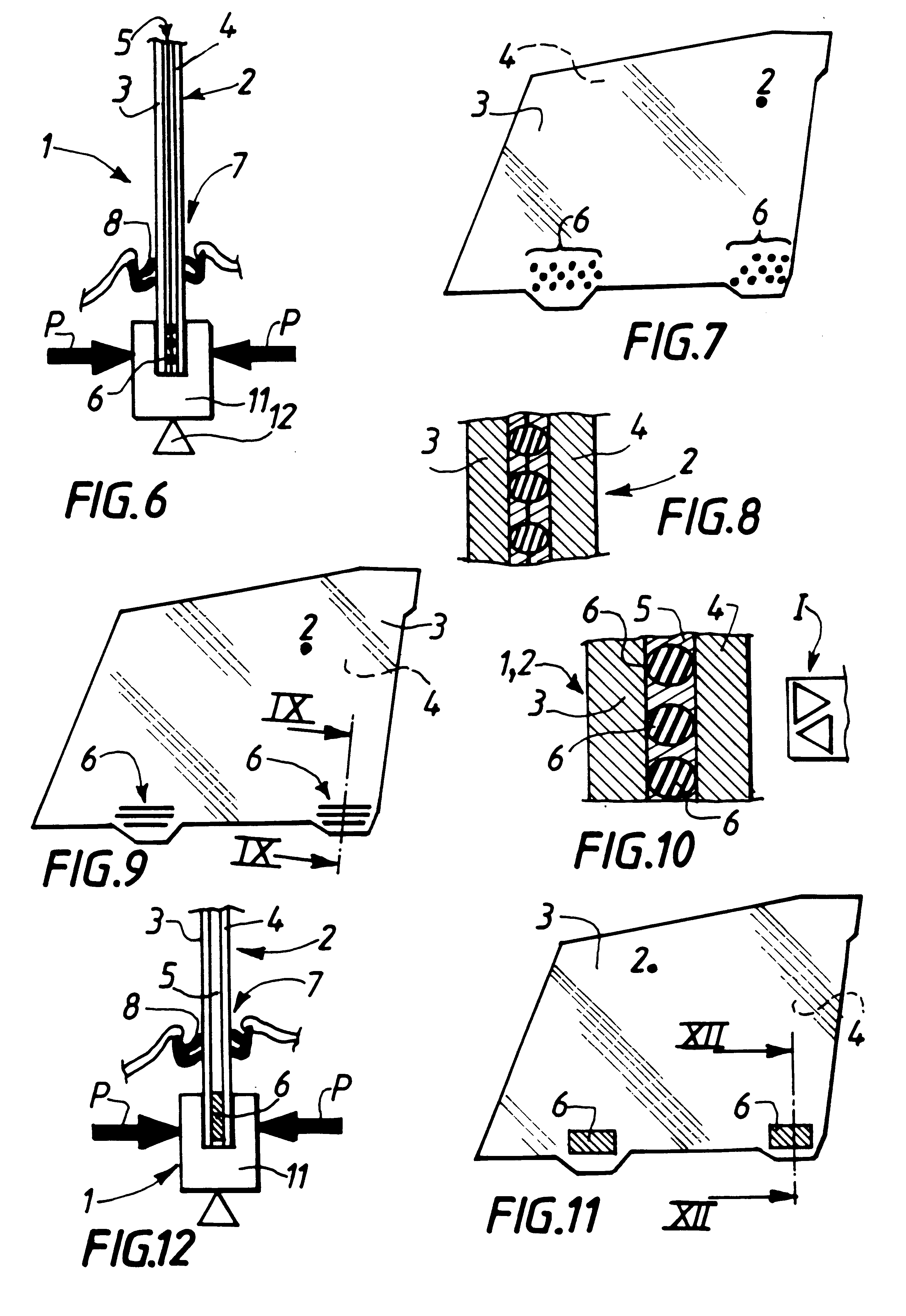
For the examples of the description, a unit 1 is shown in FIGS. 1, 4, 6, and 12.

In this case, the unit 1 is a vehicle bodywork component, and in particular a door.

The door-forming unit 1 includes a device 2 forming a laminated window.

In the figures, there can be seen a first envelope element 3, a second envelope element 4, and a deformable element 5.

The elements 3, 4, and 5 form parts of the device 2, and thus of the assembly 1.

Compression pads are shown at 6 in the figures. These pads also form parts of the device 2 and thus of the assembly 1.

The door of the assembly 1 includes a passage 7 across which the device 2 extends.

Reference is made to a reference midplane in which the device 2 generally extends. The midplane coincides with the plane of the laminations in FIGS. 3, 7, 9, and 11.

In FIGS. 1, 4, 6, and 12, the midplane extends generally in a direction perpendicular to the plane of the laminations and from top to bottom thereof.

Reference is also made to a longitudinal plane. The...


PUM

PropertyMeasurementUnit
thicknessesaaaaaaaaaa
temperaturesaaaaaaaaaa
temperatureaaaaaaaaaa

Abstract

The invention relates to assembling together at least two envelope elements with at least one deformable element between the two envelope elements so that the elements are secured together rigidly in irreversible manner, the assembled-together elements being designed to be subjected to compression stresses in a direction that at least intersects an assembly surface; bonding treatment is provided so that at least one compression pad has its first assembly surface in contact with the assembly surface of the first envelope element and so that a second assembly surface of a pad is in contact with an assembly surface of the second envelope element.

Description

The invention relates to the general technical field of assembling elements together.In particular, it relates to an assembly method, an assembly installation, a device assembled thereby, and a unit including the device.The term "assembly" is used herein to mean any operation whereby at least two hard and brittle elements are secured to each other, and also to at least one deformable element disposed between the two hard and brittle elements, rigidly and in irreversible manner.The term "irreversible" means that separating the elements will spoil them.Such assembly is common in numerous technical fields, regardless of the structure and / or the composition of the materials and / or the final purpose of the elements.Such assemblies are desirable in numerous technical fields such as building and public works, furniture, and mechanical engineering, in particular.For greater simplicity, the invention is described in the field of glazing. The scope of the invention is not limited in any way t...

Claims


Application Information

Patent Timeline
Patent Type & Authority Patents(United States)
IPC IPC(8): B32B17/10B32B17/06B60J1/17E05F11/38E06B3/663E06B3/66C03C27/12
CPCB32B17/10036B32B17/10302B32B17/10807E05F11/385E06B3/66304B60J1/17E05Y2800/33E05Y2900/55
Inventor LEGRAND, DENISSAVAETE, BERNARDSINGER, ANDRE
Owner PPG IND GLASS
Why Eureka
Try Eureka