Arrangement and method for a driving unit in a vehicle

a technology of driving unit and arrangement method, which is applied in the direction of machine control, process control, instruments, etc., can solve the problems of reducing the speed of the brake, complicated control of the engine by adjusting the amount of fuel supplied, etc., and achieves precise control of the torque and speed of the electric rotor machine. , the effect of great precision

Inactive Publication Date: 2003-01-07
SCANIA CV AB
View PDF11 Cites 23 Cited by
  • Summary
  • Abstract
  • Description
  • Claims
  • Application Information

AI Technical Summary

Benefits of technology

Controlling an engine by adjusting the amount of fuel supplied is complicated in that the fuel quantity injected is usually controlled by other conditions, some of which are intended to minimise fuel consumption. Nor is using an exhaust brake to reduce engine speed quickly an ideal practice, since it generates noise which may be disturbing.
Arranging an electric rotor machine on an output shaft of an engine is known in other contexts. These include the use of such a rotor machine as a starter motor for quickly getting the ordinary engine running. It may also be used for damping engine vibration particularly at low engine speeds, and for providing extra power during vehicle acceleration
The object of the present invention is to make gear changing in a mechanical stepped gearbox possible, without using the vehicle's clutch, by controlling torque and speed delivered to the gearbox during gear changing more quickly, more precisely and more quietly, than by using the known technology mentioned in the introduction.
This object is achieved by an arrangement which is characterised in that it incorporates an electric rotor machine connected to a connecting device. With such an electric rotor machine it is possible quickly, quietly and precisely to adjust torque delivered by the engine and its speed via the connecting device so that substantially no torque is transmitted to the gearbox during a gear change.
According to another preferred embodiment, the electric rotor machine includes a stator and a rotor, and the rotor is arranged in the connecting device. This means that the electric rotor machine can directly transmit a torque or adjust the speed of the connecting device. By way of alternative, the rotor machine may be connected via a transmission element to the connecting device, thereby making it possible to achieve a gear change between them.
The present invention also includes a method of a drive unit according to the arrangement described above. On the basis of a known practice of arranging an electric rotor machine on an engine output shaft in a vehicle, the method is characterised in that the electric rotor machine is controlled so that substantially no torque is transmitted from the connecting device to the gearbox during gear changing. Very precise control of the torque and speed of the electric rotor machine is thus possible, unlike the situation according to the known technology whereby the electric rotor machine is substantially used for supplying energy to the ordinary engine and storing braking energy. The electric rotor machine is preferably controlled, before the disengagement of a gear in the gearbox, so as to correct the torque delivered from the engine to such a level that substantially no torque is transmitted to the gearbox. It is also advantageous if the electric rotor machine, before the engagement of a gear in the gearbox, is controlled so that the connecting device is brought to a speed which is in proportion to the speed of an output shaft of the gearbox, this proportion being determined by the gear concerned. Using the electric rotor machine in the foregoing manner makes it possible quickly and with great precision to adjust the torque and speed of the engine so that the disengagement and engagement of the relevant gears can take place without being affected by torque in the gearwheels enmeshed at the time in the gearbox.

Problems solved by technology

Controlling an engine by adjusting the amount of fuel supplied is complicated in that the fuel quantity injected is usually controlled by other conditions, some of which are intended to minimise fuel consumption.
Nor is using an exhaust brake to reduce engine speed quickly an ideal practice, since it generates noise which may be disturbing.

Method used


Image

  • Arrangement and method for a driving unit in a vehicle
  • Arrangement and method for a driving unit in a vehicle

Examples


Embodiment Construction

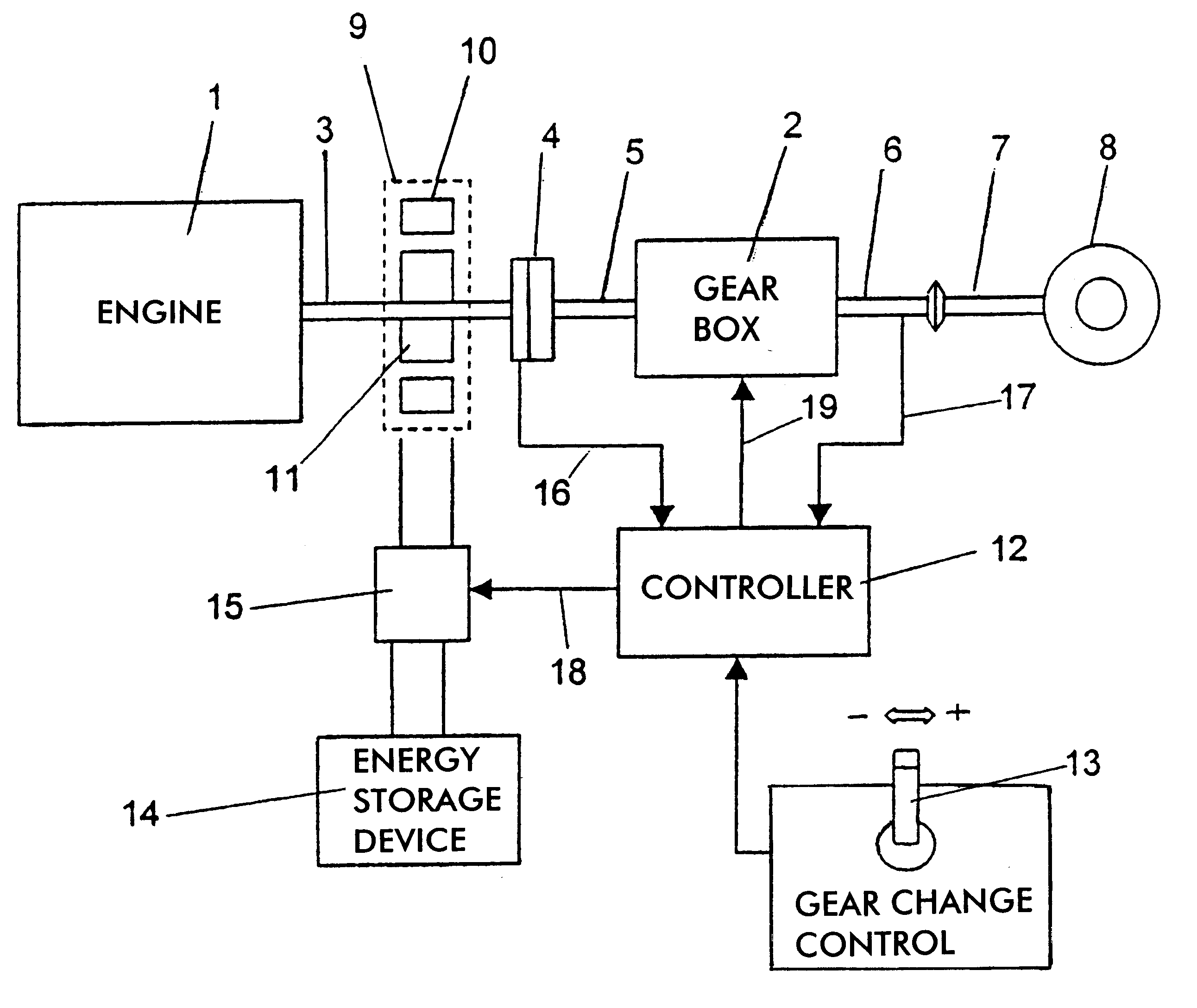
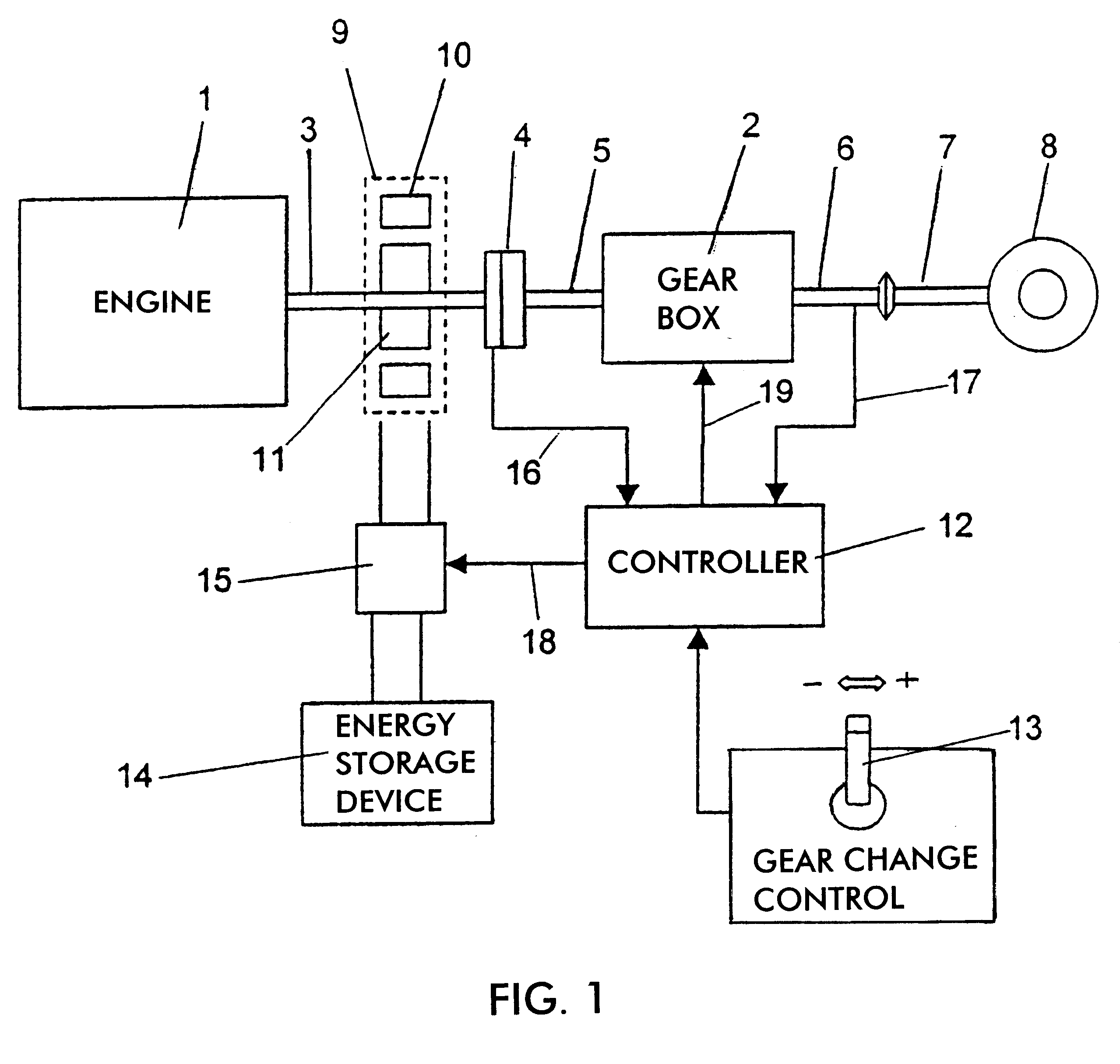
FIG. 1 depicts an arrangement, according to the present invention, for a drive unit of a vehicle. The drive unit incorporates an engine 1 and a mechanical stepped gearbox 2. A connecting device is designed to transmit rotary motion from the engine 1 to the stepped gearbox 2. The connecting device incorporates an output shaft 3 from the engine 1, a clutch 4 and an input shaft 5 to the gearbox 2. The connecting device is designed to constitute during gear changing a rigid rotating unit. After the gearbox 2, driving power supplied is led from the gearbox output shaft 6, e.g. via a propeller shaft 7, to the vehicle's driving wheels 8. The present invention makes it possible to execute gear changing in the gearbox 2 without using the clutch 4. The clutch 4 thus has no function in the present invention but is included in FIG. 1, since heavy-duty vehicles do in any case usually need a clutch function at the time of starting and stopping the vehicle. The clutch takes the form of a disc clut...


PUM


Abstract

An arrangement and a method for a drive unit of a vehicle. The drive unit incorporates an engine, a mechanical stepped gearbox and a connecting device which is designed to transmit rotary motion from the engine to the stepped gearbox. An electric rotor machine acts upon the connecting device such that substantially no torque is transmitted from the engine to the gearbox during gear changing. A control unit connected to the rotor machine may be responsive to the output shaft from the gearbox or to the speed of the engine.

Description

BACKGROUND TO THE INVENTION, AND PREVIOUS TECHNOLOGYThe present invention relates to an arrangement and a method for a drive unit of a motor vehicle. Particularly, the invention relates to an apparatus and method for control of engine torque in mechanical stepped gearboxes, wherein there is a connection between the engine and a mechanical stepped gearbox to transmit rotary motion and there are means and a method of operation for acting on the connection, so that substantially no torque is transmitted from the engine to the gearbox.In motor vehicles it is desirable to be able to change gear in a stepped gearbox without having to use the vehicle's clutch. This has been achieved, according to known technology, by the engine being controlled so that substantially no torque is transmitted from the engine to the gearbox during a gear change, i.e. while disengaging from one gear and engaging another.Methods are known from SE 504 717 correspoding to U.S. Pat. 5,859,886 and 5,866,809 and SE ...

Claims


Application Information

Patent Timeline
Patent Type & Authority Patents(United States)
IPC IPC(8): B60K6/00B60K6/04F16H61/04F16H3/08F16H3/12B60K6/485B60K6/547B60L50/16B60W10/08B60W10/10B60W20/00
CPCB60K6/485B60W10/08B60W10/11B60K6/547Y10T477/6433B60L2240/441B60L2240/486B60W20/00B60W2510/0638B60W2510/104F16H3/126F16H2061/0422F16H2306/44F16H2306/46Y10S903/945Y10S903/919Y02T10/6226Y10T477/6437Y02T10/62B60W20/40
Inventor STRANDELL, GUNNARWIKSTROM, HANS
Owner SCANIA CV AB
Why Eureka
Try Eureka